Labor-saving manually-operated wire rope cutting device

A cutting device and wire rope technology, applied in the field of manual wire rope cutting devices, can solve the problems of increasing the quality of the device, delaying time, labor-intensive danger, etc., and achieve the effects of improving cutting efficiency, saving operating time, and facilitating collection

Inactive Publication Date: 2017-05-31
郑州吉音动漫科技有限公司
View PDF1 Cites 2 Cited by
  • Summary
  • Abstract
  • Description
  • Claims
  • Application Information

AI Technical Summary

Problems solved by technology

[0002] It is often necessary to cut the wire rope during underground operations. Since gas cutting cannot be used, and the cutting speed is too slow with a hacksaw, at present, the rough method of hammering or chopping with an ax is generally used, that is, the wire rope is placed on the corners of the rail or vehicle. , break it with a sledgehammer, and when the wire rope is thick, use a sledgehammer to hit the axe, and use the blade of the axe to cut off the wire rope through the impact force of the sledgehammer. This method is extremely unscientific, and it is laborious and dangerous to operate. , especially when the wire rope is thicker, it is more dangerous to operate, and it is easy to cause industrial accidents; the Chinese patent application number 201120147388.X proposes a wire rope scissors that basically solve the above problems; The jack increases the quality of the device, and the jack is too slow in operation, which delays time and reduces the speed of wire rope cutting, which is not convenient for wire rope cutting

Method used


Image

  • Labor-saving manually-operated wire rope cutting device
  • Labor-saving manually-operated wire rope cutting device
  • Labor-saving manually-operated wire rope cutting device

Examples


Embodiment Construction

[0016] The technical solution of this patent will be described in further detail below in conjunction with specific embodiments.

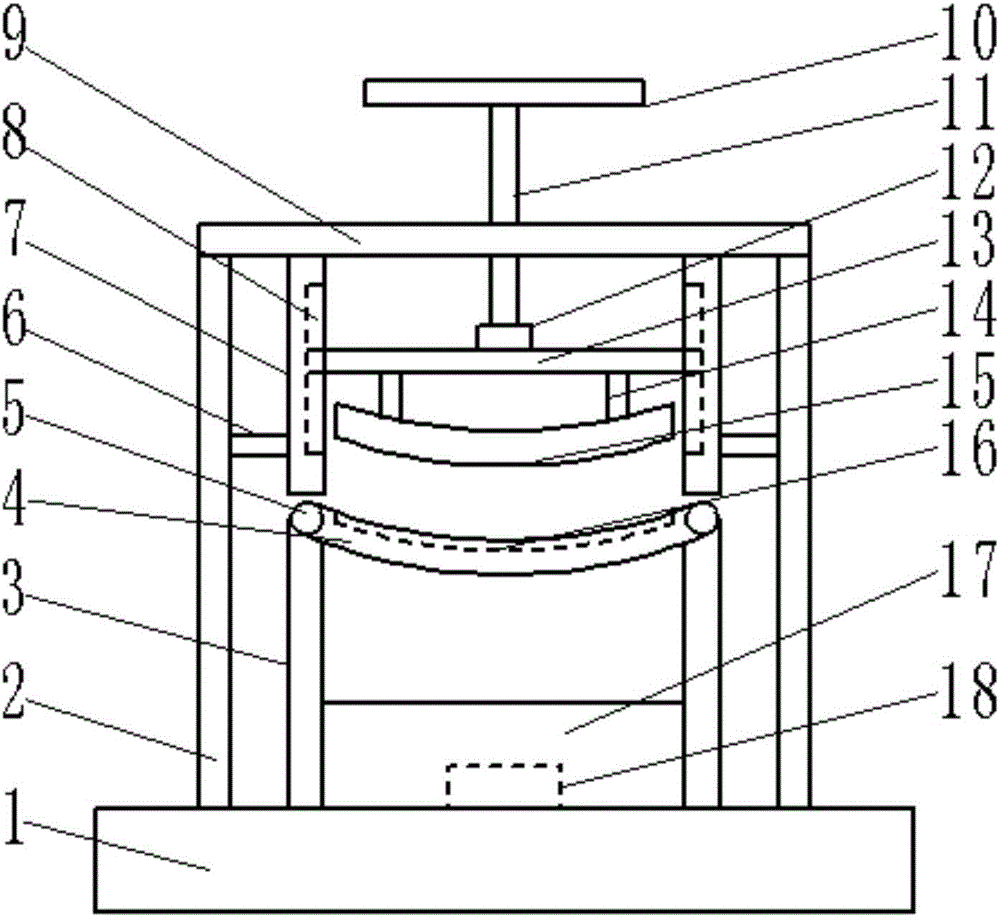
[0017] See Figure 1-3 , A labor-saving manual wire rope cutting device, including a base 1, a support plate 9 and a cutting knife 15. The base 1 is provided with a collection box 17 in the middle, and the collection box 17 is provided with a column 3 on the outside, and a base outside the column 3 1 is provided with a pillar 2; the collection box 17 is fixed on the upper surface of the base 1, and a magnet 18 is placed in the collection box 17 to absorb the filaments scattered during cutting; the pillars 3 are two in total, which are distributed On the left and right sides of the collection box 17, hinges 5 are provided on the top of the column 3, and the column 3 is connected with a support block 4 through the hinge 5; the support block 4 is arranged on the top of the two columns 3, and the shape of the support block 4 is round The top of the suppo...


PUM


Abstract

The invention provides a labor-saving manually-operated wire rope cutting device. The device comprises a base, a support plate and a cutting knife, wherein a collecting box is arranged at the middle part of the base; stand columns are arranged on the outer side of the collecting box; support columns are arranged on the base on the outer side of the stand columns; a support block is connected to the stand columns through hinges; a knife groove is formed in the top of the support block; a screw hole is formed in the middle part of the support plate; guide plates are arranged under the support plate; a guide groove is formed in the inner side of each of the guide plates; connecting rods are arranged on the upper part of the cutting knife; the upper ends of the connecting rods are connected to the lower part of a limiting rod; a connecting piece is arranged at the upper part of the limiting rod; a threaded rod is connected to the upper part of the connecting piece; a rotating handle is arranged at the top of the threaded rod; and the connecting piece consists of a protective cover, a bearing, a rod head and a sealing ring. According to the device disclosed by the invention, the threaded rod can rotate up or down to drive the cutting knife to rise or fall and cut a wire rope, so that the force of an operator for cutting the wire rope is reduced, besides, the operating time is saved, and the cutting efficiency is improved.

Description

Technical field [0001] The invention relates to a wire rope cutting device, in particular to a manual wire rope cutting device capable of saving labor. Background technique [0002] It is often necessary to cut the wire rope in the process of underground operation. Since the gas cutting operation cannot be used, the speed of breaking with a hacksaw is too slow. At present, the relatively rude hammering and axe methods are generally used, that is, the wire rope is placed on the corners of the rail or vehicle. , Use a sledgehammer to break it. When the wire rope is thick, use the sledgehammer to hit the axe, and use the blade of the axe to cut the wire rope through the impact of the sledgehammer. This method is extremely unscientific, and the operation is laborious and dangerous. , Especially when the steel wire rope is thicker, it is more dangerous to operate and can easily cause work-related accidents; the Chinese patent application number 201120147388.X proposes a steel wire rop...

Claims


Application Information

Patent Timeline
Patent Type & Authority Applications(China)
IPC IPC(8): B21F11/00
CPCB21F11/00
Inventor 不公告发明人
Owner 郑州吉音动漫科技有限公司
Why Eureka
Try Eureka