
A self-suppression and controlled flow double-nozzle electromagnetic composite casting device

An electromagnetic compounding, double nozzle technology, applied in the field of steel casting, can solve problems such as continuous production, and achieve the effects of suppressing molten steel mixing, reducing temperature difference and density difference, and suppressing impact

Active Publication Date: 2018-10-09
CHONGQING UNIV
View PDF5 Cites 0 Cited by
  • Summary
  • Abstract
  • Description
  • Claims
  • Application Information

AI Technical Summary

Problems solved by technology

[0005] In order to realize effective dual-steel composite casting, the most critical issue is how to effectively suppress the mixing of molten steel at the interface of the two molten steels without affecting the casting process and the quality of the slab, so as to ensure efficient and high-quality composite casting. Continuous casting, thus solving the technical problems of producing high-quality composite billets
Aiming at the deficiencies of the prior art, the present invention proposes a self-inhibiting and control-flow type double-nozzle electromagnetic composite casting device based on the multi-method control method and process control method of the flow field to solve the problem of the two kinds of molten steel in the prior art. Technical issues such as mixing at the interface and continuous production

Method used


Image

  • A self-suppression and controlled flow double-nozzle electromagnetic composite casting device
  • A self-suppression and controlled flow double-nozzle electromagnetic composite casting device
  • A self-suppression and controlled flow double-nozzle electromagnetic composite casting device

Examples


Embodiment Construction

[0023] The present invention will be described in further detail below in conjunction with specific embodiments.

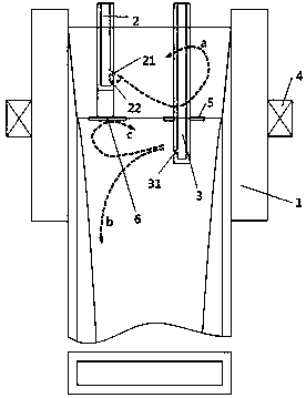
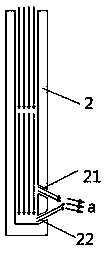
[0024] A self-inhibiting and flow-controlled double nozzle electromagnetic composite casting device, such as Figure 1-3 As shown, it includes a crystallizer 1, a self-suppressing submerged double nozzle device and an electromagnetic field generating device; the self-suppressing submerged double nozzle device includes a vertically arranged short submerged nozzle 2 and a long submerged nozzle 3, two Both are in the shape of a tube with an upper end opening; the insertion depth of the short submerged nozzle 2 in the crystallizer 1 is less than the insertion depth of the long submerged nozzle 3; the short submerged nozzle 2 and the long submerged nozzle The lower end of the nozzle 3 is respectively provided with a short submerged tapping side hole 21 and a long submerged tapping side hole 31 inclined downward, which are respectively used to lead out the upper layer m...


PUM


Abstract

The invention discloses a self-restrained flow controlling type double water gap electromagnetic composite casting device comprising a crystallizer, a self-restrained immersion type double water gap device and an electromagnetic field generating device. The self-restrained immersion type double water gap device comprises a short-type immersion type water gap and a long-type immersion type water gap which are arranged vertically and in pipe shapes with the upper ends being open. The insertion depth of the short-type immersion type water gap is smaller than the insertion depth of the long-type immersion type water gap. A downward-inclined side hole and a flow restraining tapping side hole are formed in the lower end of the short-type immersion type water gap, and a downward-inclined tapping side hole is formed in the lower end of the long-type immersion type water gap. The electromagnetic field generating device comprises a plurality of electromagnets, and the electromagnets are arranged in the circumferential direction of the crystallizer and used for producing a horizontal magnetic field and acting on the interface of upper-layer molten steel and lower-layer molten steel so as to restrain mixing of the upper-layer molten steel and lower-layer molten steel. Under the premise of guaranteeing the quality of a casting blank, mixing of the two kinds of molten steel in the interface is effectively restrained, and therefore, efficient and high-quality composite continuous casting is achieved.

Description

technical field [0001] The invention belongs to the technical field of steel material casting, and in particular relates to a self-inhibiting and flow-controlling double nozzle electromagnetic composite casting device. Background technique [0002] At present, the methods for producing stainless steel / carbon steel clad plates mainly include rolling clad method, explosive welding method and casting and rolling method, but the yield and output of these methods are very low. In 1978, Manokhin et al. proposed a method of producing composite continuous casting slabs using double molds, that is, the slabs cast in the first mold were introduced into the second mold, and then another molten steel was coated. On its surface, the composite casting slab is pulled out. Although this process belongs to continuous production, the operation is complicated, difficult to control, and its application is limited. [0003] In the late 1990s, Japan’s Takeuchi et al. proposed a method of using a...

Claims


Application Information

Patent Timeline
Patent Type & Authority Patents(China)
IPC IPC(8): B22D11/041B22D11/11
CPCB22D11/007B22D11/0403B22D11/041B22D11/11
Inventor 龙木军姜文祥陈登福段华美俞晟曹俊生徐佩喻恒松
Owner CHONGQING UNIV
Learn More