Device for taking out bearing ring casting parts
A technology for removing devices and castings, which is applied in the field of bearing tools and equipment, and can solve problems such as being unsuitable for automatic removal of bearing rings.
- Summary
- Abstract
- Description
- Claims
- Application Information
AI Technical Summary
Problems solved by technology
Method used
Image
Examples
Embodiment 1
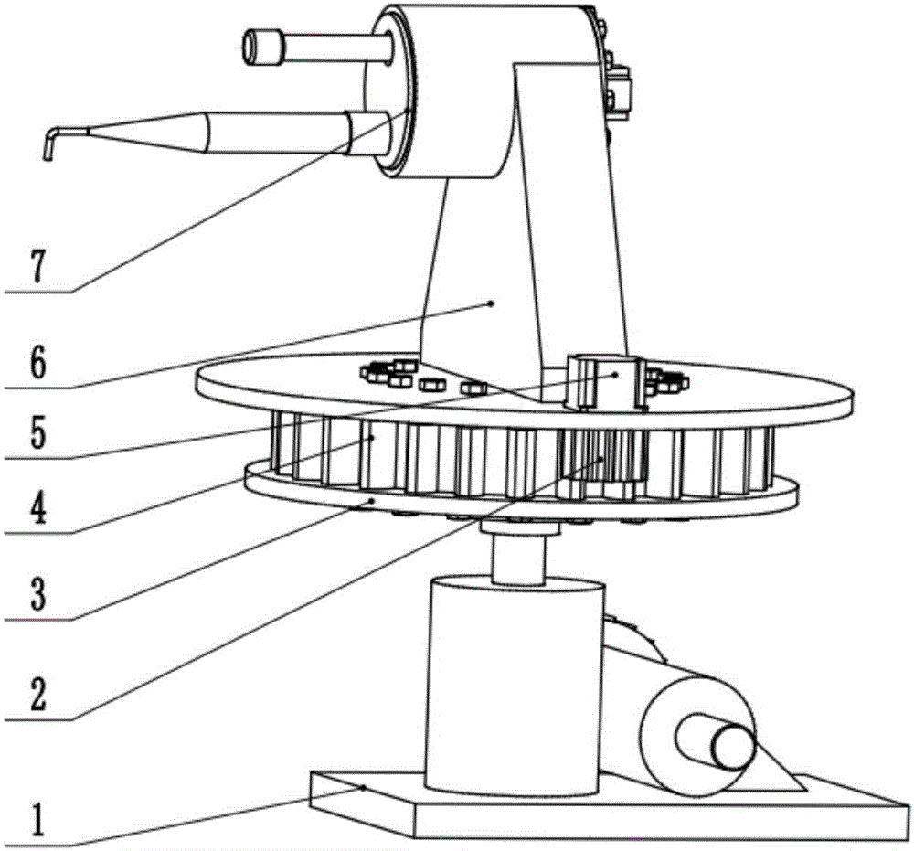
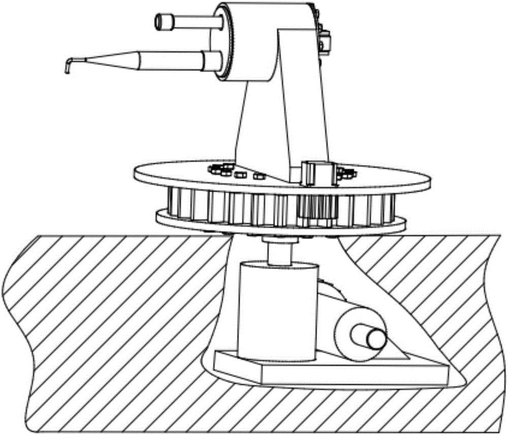
[0023] as attached figure 1 , attached figure 2 As shown, a bearing ring casting removal device is composed of a worm gear lifter 1, a pinion 2, a slewing support lower plate 3, a slewing support 4, a slewing support motor 5, a housing 6, a rotating device 7, a detection device and a control The device is composed of the lower surface of the slewing support lower plate 3 installed on the worm gear lifter 1, the upper surface of the slewing support lower plate 3 is installed with the slewing support 4, the casing 6 is installed above the slewing support 4, and the slewing support motor 5 is installed on the casing 6 Above, the pinion 2 is installed on the output shaft of the slewing support motor 5, and the rotating device 7 is installed inside the housing 6. In the rotating device, the rotating motor 71 is installed on the rotating cylinder 76, and the telescopic device 72 is installed inside the rotating cylinder 76. The cylinder 73 is installed on the cylinder mounting pla...
Embodiment 2
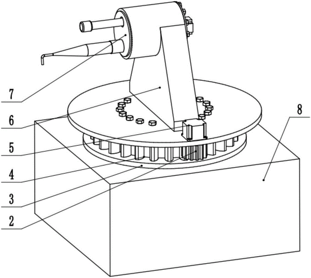
[0027] like figure 2 As shown, a bearing ring casting removal device is composed of a worm gear lifter 1, a pinion 2, a slewing support lower plate 3, a slewing support 4, a slewing support motor 5, a housing 6 and a rotating device 7. The slewing support The lower surface of the lower plate 3 is installed on the worm gear lifter 1, the upper surface of the slewing support lower plate 3 is installed with the slewing support 4, and the housing 6 is installed above the slewing support 4, the slewing support motor 5 is installed on the housing 6, and the pinion 2 is installed On the output shaft of the slewing support motor 5, the rotating device 7 is installed inside the housing 6. In the rotating device, the rotating motor 71 is installed on the rotating cylinder 76, the telescopic device 72 is installed inside the rotating cylinder 76, and the cylinder 73 is installed on the cylinder. On the plate 75, one side of the cylinder mounting plate 75 is fixedly connected on the rota...
PUM
 Abstract
Description
Claims
Application Information
 - R&D
- Intellectual Property
- Life Sciences
- Materials
- Tech Scout
- Unparalleled Data Quality
- Higher Quality Content
- 60% Fewer Hallucinations
Browse by: Latest US Patents, China's latest patents, Technical Efficacy Thesaurus, Application Domain, Technology Topic, Popular Technical Reports.
© 2025 PatSnap. All rights reserved.Legal|Privacy policy|Modern Slavery Act Transparency Statement|Sitemap|About US| Contact US: help@patsnap.com


