Milling cutter

A technology of milling cutter and rake face, which is applied in the direction of milling cutter, milling cutting blade, milling machine equipment, etc. It can solve the problems that it is difficult to use special materials and processes, easy to wear, affect the processing efficiency and yield of machine tools, etc.

Active Publication Date: 2017-05-31
海南中智康弘精工技术有限公司
View PDF10 Cites 0 Cited by
  • Summary
  • Abstract
  • Description
  • Claims
  • Application Information

AI Technical Summary

Problems solved by technology

[0002] In the current processing of difficult-to-machine materials, composite materials, and superimposed materials, with the development of industrialization, the current market demand for milling cutters in my country is relatively large, especially for processing titanium alloys and high-temperature alloy milling cutters. There are also many types of requirements, and the existing milling cutters usually have a relatively simple structure, and are only suitable for conventional processing during processing, and are difficult to use in special materials and processes, which in turn affects the processing efficiency and yield of machine tools.
In addition, the existing milling cutters tend to cause stress concentration and easy wear during the processing process, which affects the service life of the milling cutter

Method used


Image

  • Milling cutter
  • Milling cutter
  • Milling cutter

Examples


Embodiment Construction

[0022] In order to make the purpose, technical solutions and advantages of the embodiments of the present invention clearer, the technical solutions in the embodiments of the present invention will be clearly and completely described below in conjunction with the drawings in the embodiments of the present invention. Obviously, the described embodiments It is a part of embodiments of the present invention, but not all embodiments. Based on the embodiments of the present invention, all other embodiments obtained by persons of ordinary skill in the art without making creative efforts belong to the protection scope of the present invention.

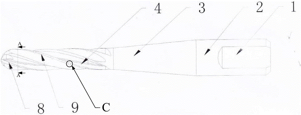
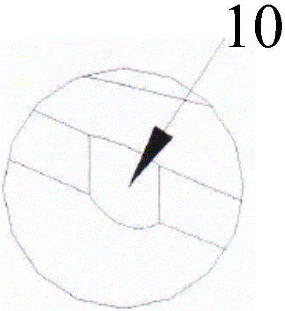
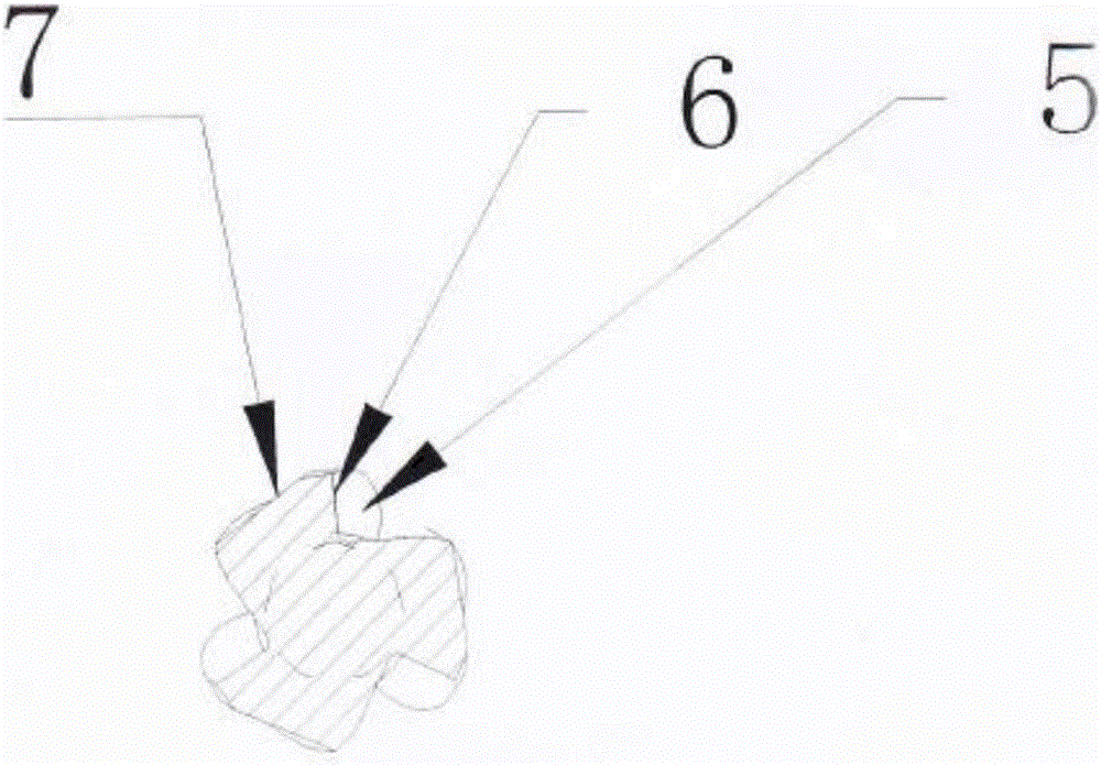
[0023] Please refer to Figure 1-Figure 5 , figure 1 Schematic diagram of the structure of the milling cutter provided by the embodiment of the present invention; figure 2 for figure 1 Schematic diagram of the partial enlarged structure of C; image 3 for figure 1 A-A cross-sectional structural schematic diagram of ; Figure 4 A schema...


PUM


Abstract

The invention discloses a milling cutter. The milling cutter comprises a cutting portion. Spherical blade portions are arranged on the top of the cutting portion. Each spherical blade portion comprises a front knife face, a rear knife face and a cutting edge located between the front knife face and the rear knife face. Multiple side blade portions extending in a spiral shape in the axial direction are arranged on the peripheral wall of the cutting portion. Multiple circular arc blades are arranged on each side blade portion. Due to arrangement of the circular arc blades on the side blade portions, the length of the side blade portions is increased to a certain degree, the effects of chipping separation, chipping discharge and stress concentration reduction are achieved, the machining mechanism is improved, and the service life of the milling cutter is prolonged.

Description

technical field [0001] The invention relates to the technical field of machining tools, in particular to a milling cutter. Background technique [0002] In the current processing of difficult-to-machine materials, composite materials, and superimposed materials, with the development of industrialization, the current market demand for milling cutters in my country is relatively large, especially for processing titanium alloys and high-temperature alloy milling cutters. There are also many types of requirements, and the existing milling cutters usually have a relatively simple structure, and are only suitable for conventional processing during processing, and are difficult to use in special materials and processes, which in turn affects the processing efficiency and yield of machine tools. . In addition, during the processing of the existing milling cutter, it is easy to cause stress concentration and easy wear, which affects the service life of the milling cutter. [0003] Th...

Claims


Application Information

Patent Timeline
Patent Type & Authority Applications(China)
IPC IPC(8): B23C5/10
CPCB23C5/1018B23C2200/24B23C2200/32B23C2210/20
Inventor 田振平
Owner 海南中智康弘精工技术有限公司
Why Eureka
Try Eureka