
Automatic capping machine

A capping and automatic technology, applied in the direction of metal processing equipment, metal processing, manufacturing tools, etc., can solve the problems of low operating efficiency and difficulty in meeting the needs of industrialized production

Active Publication Date: 2019-04-12
无锡进源科技开发有限公司
View PDF11 Cites 0 Cited by
  • Summary
  • Abstract
  • Description
  • Claims
  • Application Information

AI Technical Summary

Problems solved by technology

[0002] Before the three-way pipe leaves the factory, plastic rubber caps need to be set on the three ends respectively. In the prior art, there is no automatic equipment to complete the above operation process. The capping of the three-way pipe is generally done manually. completed, the operation efficiency is low, and it is difficult to meet the needs of industrialized production

Method used


Image

  • Automatic capping machine
  • Automatic capping machine
  • Automatic capping machine

Examples


Embodiment Construction

[0018] The specific embodiments of the present invention will be further described below in conjunction with the accompanying drawings.

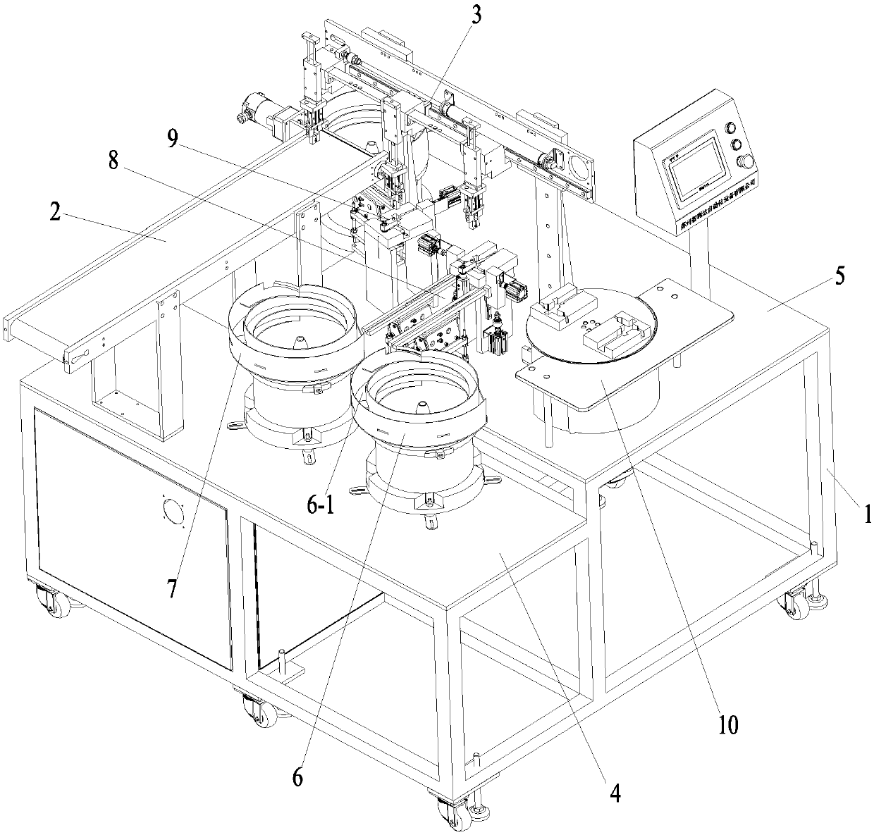
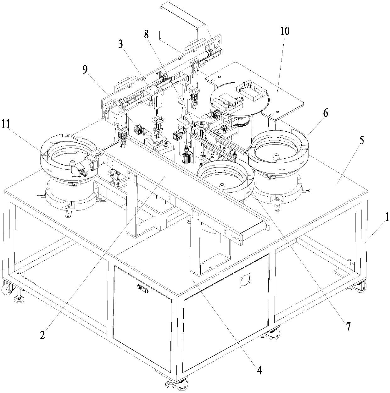
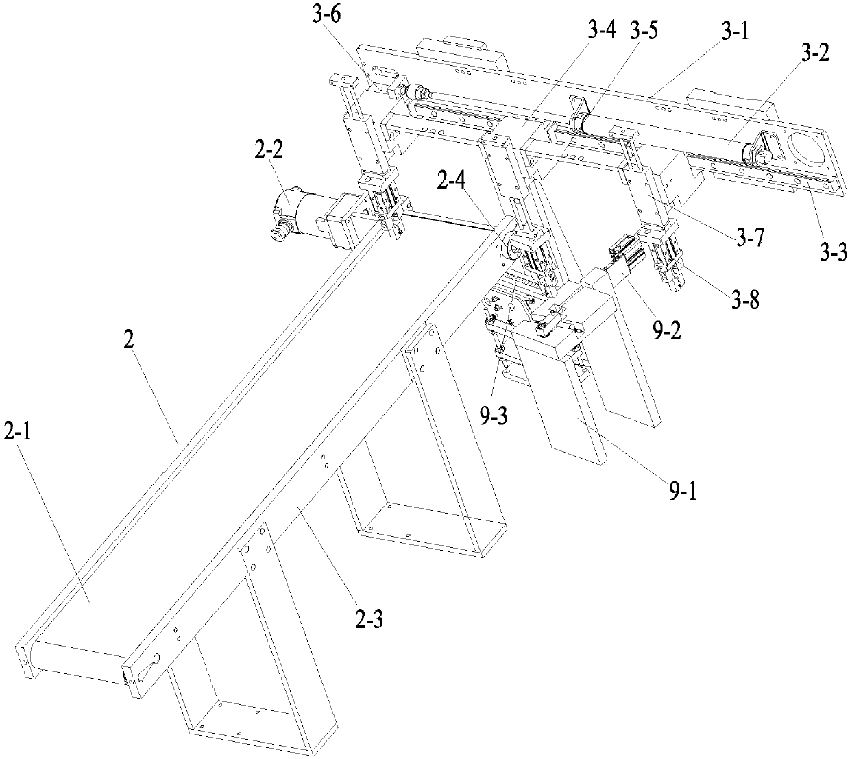
[0019] Figure 1~6 Among them, including support 1, unloading device 2, conveyor belt 2-1, driving motor 2-2, unloading bracket 2-3, conveying roller 2-4, retrieving device 3, retrieving bracket horizontal plate 3-1, Horizontal moving cylinder 3-2, guide rail 3-3, slider 3-4, positioning plate 3-5, in-position pressure head pressing plate 3-6, lifting cylinder 3-7, jaw cylinder 3-8, vibration plate bottom plate 4. Feeding bottom plate 5, first vibrating plate 6, material channel 6-1, second vibrating plate 7, first cap pressing device 8, longitudinal support frame 8-1, I-beam bottom plate 8-2, cap pushing cylinder 8-3, rotary cylinder 8-4, briquetting block 8-5, first track 8-6, connecting plate 8-7, second pressing cap device 9, bracket plate 9-1, pressing cylinder 9-2, the first Two rails 9-3, spare parts device 10, stepping motor 10-1, ...


PUM


Abstract

The invention belongs to the technical field of mechanical equipment for packaging, and relates to an automatic capping machine. The automatic capping machine comprises a support. A vibration disk base plate of the support is provided with a first vibration disk and a second vibration disk. A fetching device is arranged on a fetching base plate of the support. A first cap pressing device is arranged between the first and second vibrating disks and the fetching device. The first vibrating disk and the second vibrating disk are used for feeding to first cap pressing device. A discharging device is further arranged on the top surface of a frame. A second cap pressing device is arranged between the discharging device and the first cap pressing device. The second cap pressing device is fed through a third vibration disk arranged on the fetching base plate. A spare-part device is arranged on the lateral portion, corresponding to the first cap pressing device, of the fetching base plate. A workpiece on the first cap pressing device is transferred to the second cap pressing cap device through the fetching device. By using the capping machine, the capping operation of T-branch pipes can be completed efficiently and quickly and the production efficiency is improved.

Description

technical field [0001] The invention belongs to the technical field of packaging machinery and equipment, and relates to an automatic capping machine. Background technique [0002] Before the three-way pipe leaves the factory, plastic rubber caps need to be set on the three ends respectively. In the prior art, there is no automatic equipment to complete the above operation process. The capping of the three-way pipe is generally done manually. Complete, the operation efficiency is low, it is difficult to meet the production needs of industrialization. Contents of the invention [0003] In view of the above problems, the present invention provides an automatic capping machine, which can efficiently and quickly complete the capping operation of three-way pipes and improve production efficiency. [0004] According to the technical scheme of the present invention: an automatic capping machine, it is characterized in that: it comprises a bracket, a first vibrating plate and a s...

Claims


Application Information

Patent Timeline
Patent Type & Authority Patents(China)
IPC IPC(8): B23P19/00B23P19/027
CPCB23P19/001B23P19/027
Inventor 王少波
Owner 无锡进源科技开发有限公司
Learn More