
Circular plate type automatic polishing machine

A technology of automatic polishing and polishing mechanism, which is used in surface polishing machine tools, grinding/polishing equipment, automatic grinding control devices, etc., can solve the problem of low work efficiency, inability to realize automatic compensation of grinding wheel wear, and poor polishing surface quality. Guarantee and other issues to achieve the effect of improving production efficiency, ensuring polishing quality, and improving polishing effect

Inactive Publication Date: 2017-05-31
江门市兄弟机械制造有限公司
View PDF6 Cites 6 Cited by
  • Summary
  • Abstract
  • Description
  • Claims
  • Application Information

AI Technical Summary

Problems solved by technology

[0002] The polishing machines on the existing market are generally suitable for the processing of workpieces with regular-shaped surfaces. The polishing of some small irregular workpiece surfaces is a major problem in this field, and the existing polishing machines cannot automatically compensate for the wear of the grinding wheel. The quality of the polished surface is not guaranteed due to the wear of the grinding wheel
In addition, the existing polishing machines generally can only process a single part, and it is a semi-automatic operation, with low work efficiency

Method used


Image

  • Circular plate type automatic polishing machine

Examples


Embodiment Construction

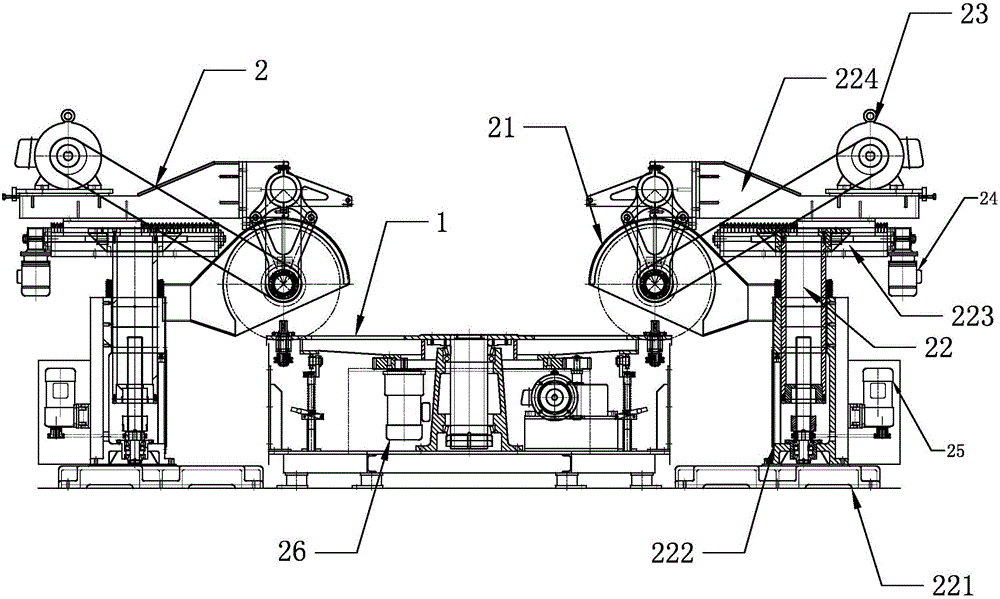
[0015] refer to figure 1 , the disc automatic polishing machine of the present invention includes a mounting table 1 for installing a workpiece and a polishing mechanism 2 for polishing the workpiece, and the polishing mechanism 2 includes a polishing wheel 21 and a frame 22 for installing the polishing wheel 21, The mounting table 1 is a rotatable disc, and the frame 22 includes a fixed base 221, on which a column 222 is installed, and the column 222 can slide back and forth along the surface of the base 221, and the column 222 The first support frame 223 that can move up and down along the column 222 is sleeved, the polishing wheel 21 is installed on the first support frame 223, and the upper surface of the first support frame 223 is equipped with a The second supporting frame 224 of action, described second supporting frame 224 is provided with the first motor 23 that drives polishing wheel 21 to rotate, preferably, described second supporting frame 224 is connected and is ...


PUM


Abstract

The invention discloses a circular plate type automatic polishing machine. The circular plate type automatic polishing machine comprises a workpiece mounting table and workpiece polishing mechanisms. Each polishing mechanism comprises a polishing wheel and a frame for mounting of the corresponding polishing wheel, and the mounting table is a rotatable circular plate. Each frame comprises a fixed base, a vertical column is mounted on each base and capable of sliding back and forth along the surface of the corresponding base, and a first supporting frame capable of moving up and down along each vertical column sleeves the corresponding vertical column. The polishing machine further comprises a PLC (programmable logic controller) control system and sensors. The circular plate type automatic polishing machine has advantages that each polishing head is capable of moving longitudinally, vertically and bilaterally, the angle and the direction of each polishing wheel can be adjusted in real time according to workpiece surface conditions and sand wheel abrasion conditions to guarantee workpiece surface polishing quality; the whole polishing machine is connected with the PLC system and capable of realizing automatic compensation, polishing force uniformity is guaranteed, great polishing effects are achieved, and multiple workpieces can be machined at the same time, so that production efficiency is greatly improved.

Description

technical field [0001] The invention relates to the field of polishing equipment, in particular to an automatic disc polishing machine. Background technique [0002] The polishing machines on the existing market are generally suitable for the processing of workpieces with regular-shaped surfaces. The polishing of some small irregular workpiece surfaces is a major problem in this field, and the existing polishing machines cannot automatically compensate for the wear of the grinding wheel. The quality of the polished surface cannot be guaranteed due to the wear of the grinding wheel. In addition, the existing polishing machines generally can only process a single part, and are semi-automatic, with low work efficiency. Contents of the invention [0003] The present invention aims to solve one of the above-mentioned technical problems in the related art at least to a certain extent. For this reason, the present invention proposes a kind of disc automatic polishing machine. ...

Claims


Application Information

Patent Timeline
Patent Type & Authority Applications(China)
IPC IPC(8): B24B29/02B24B27/00B24B41/06B24B41/02B24B47/12B24B51/00
CPCB24B29/02B24B27/0076B24B41/02B24B41/06B24B47/12B24B51/00
Inventor 陈炳巽
Owner 江门市兄弟机械制造有限公司
Learn More