Hydraulic ejection nut disassembly mechanism

An ejector type, hydraulic type technology, applied in the direction of hand-held tools, manufacturing tools, etc., can solve the problems of corrosion, inability to disassemble, etc., to achieve the effect of easy portability, simple structure, and solve the problems of disassembly and replacement.

Inactive Publication Date: 2017-05-31
梁芳歌
View PDF0 Cites 2 Cited by
  • Summary
  • Abstract
  • Description
  • Claims
  • Application Information

AI Technical Summary

Problems solved by technology

In the past, the nuts and bolts were usually cut off by gas welding. However, in some special working conditions, it is sometimes strictly forbidden to use fire welding operations, such as coal powder bunkers in power plants, high-pressure and high-temperature pipelines in oil pipelines, etc. Replacing nuts and bolts is even more frustrating
Concrete sleeper spike nuts will corrode on the spike bolts due to maintenance and environmental reasons and cannot be removed. If the bolts are damaged by gas welding, other tools must be used to remove the nuts

Method used


Image

  • Hydraulic ejection nut disassembly mechanism

Examples


Embodiment 1

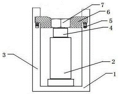
[0013] This embodiment provides a hydraulic ejector nut removal mechanism, which is characterized in that: the fully automatic nut removal device includes a fixed mounting frame (1), a jacking drive cylinder (2), a side column (3), a telescopic piston (4), fixed bolt (5), fixed clamp block (6), nut (7);

[0014] Among them: including the fixed fixture, fixed installation frame (1) and jacking drive cylinder (2), the middle position of the fixed installation frame (1) is equipped with jacking drive cylinder (2), and the telescopic piston of jacking drive cylinder (2) ( 4) Arrest the core position of the nut (7). There are two fixed clips (6) on both sides of the nut (7). The fixed clips (6) are set on both sides of the fixed mounting bracket (1) The inner side of the jamb (3).

[0015] The fixed installation frame (1) is U-shaped.

[0016] The jacking drive cylinder (2) is a pneumatic cylinder.

Embodiment 2

[0018] This embodiment provides a hydraulic ejector nut removal mechanism, which is characterized in that: the fully automatic nut removal device includes a fixed mounting frame (1), a jacking drive cylinder (2), a side column (3), a telescopic piston (4), fixed bolt (5), fixed clamp block (6), nut (7);

[0019] Among them: including the fixed fixture, fixed installation frame (1) and jacking drive cylinder (2), the middle position of the fixed installation frame (1) is equipped with jacking drive cylinder (2), and the telescopic piston of jacking drive cylinder (2) ( 4) Arrest the core position of the nut (7). There are two fixed clips (6) on both sides of the nut (7). The fixed clips (6) are set on both sides of the fixed mounting bracket (1) The inner side of the jamb (3).

[0020] The fixed installation frame (1) is U-shaped.

[0021] The jacking drive cylinder (2) is a hydraulic cylinder.


PUM


Abstract

The invention discloses a hydraulic ejection nut disassembly mechanism. The hydraulic ejection nut disassembly mechanism is characterized by comprising a fixed mounting frame, a jacking driving cylinder, side columns, an extension piston, fixed bolts, fixed clamping blocks and a nut, and further comprises a fixed fixture, the fixed mounting frame and the jacking driving cylinder; the fixed mounting frame is U-shaped; the jacking driving cylinder is arranged in the middle position of the fixed mounting frame; the extension piston of the jacking driving cylinder is abutted against a nut core position; two fixed clamping blocks are located on two sides of the nut; the fixed clamping blocks are arranged on the inner sides of the side columns on two sides of the fixed mounting frame through the fixed bolts; and the driving cylinder can be a hydraulic cylinder or a pneumatic cylinder. The hydraulic ejection nut disassembly mechanism has the advantages of: simple structure, small size, convenience in carrying, no use of fire, no use of electricity, no damage of bolt screw threads, convenience, speediness, safety, and efficient solution of the disassembly and replacement difficulties of bolts and nuts.

Description

technical field [0001] The invention relates to the technical field of nut removal tools, and in particular provides a hydraulic ejector nut removal mechanism. Background technique [0002] It is very difficult to disassemble the nuts that are widely used in open-air high-temperature or corrosive environments in industrial production. In the past, the nuts and bolts were usually cut off by gas welding. However, in some special working conditions, it is sometimes strictly forbidden to use fire welding operations, such as coal powder bunkers in power plants, high-pressure and high-temperature pipelines in oil pipelines, etc. Replacing nuts and bolts is even more frustrating. Concrete sleeper spike nuts will corrode on the spike bolts due to maintenance and environmental reasons and cannot be removed. If the bolts are damaged by gas welding, other tools must be used to remove the nuts. Contents of the invention [0003] The object of the present invention is to solve the ab...

Claims


Application Information

Patent Timeline
Patent Type & Authority Applications(China)
IPC IPC(8): B25B27/14
CPCB25B27/14
Inventor 梁芳歌
Owner 梁芳歌
Why Eureka
Try Eureka