
Automatic assembly line of plastic trays

A technology for plastic pallets and assembly lines, which is applied in the field of automatic assembly lines for plastic pallets, can solve the problems of different specifications of plastic pallets, easy to make mistakes, and high labor intensity, so as to reduce the labor intensity of workers, realize the automation of production and assembly, and improve work efficiency.

Active Publication Date: 2017-05-31
宁波海天智联科技有限公司
View PDF4 Cites 12 Cited by
  • Summary
  • Abstract
  • Description
  • Claims
  • Application Information

AI Technical Summary

Problems solved by technology

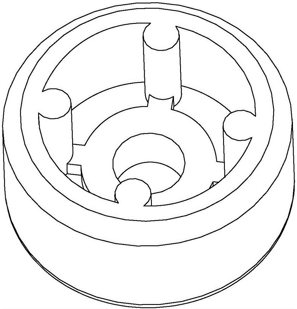
Because the front and back of the feet have different structures, it is necessary to arrange the feet in a uniform posture before installing the feet to facilitate subsequent installation. However, the arrangement of the feet is manual. On the one hand, it is easy to make mistakes because of a long-term single operation. On the one hand, after the feet are installed on one side of the plastic pallet, the plastic pallet needs to be turned over, which is labor-intensive; in addition, the specifications of the plastic pallet are different, and there is currently no suitable equipment that can replace the manual completion of the above process

Method used


Image

  • Automatic assembly line of plastic trays
  • Automatic assembly line of plastic trays
  • Automatic assembly line of plastic trays

Examples


Embodiment 1

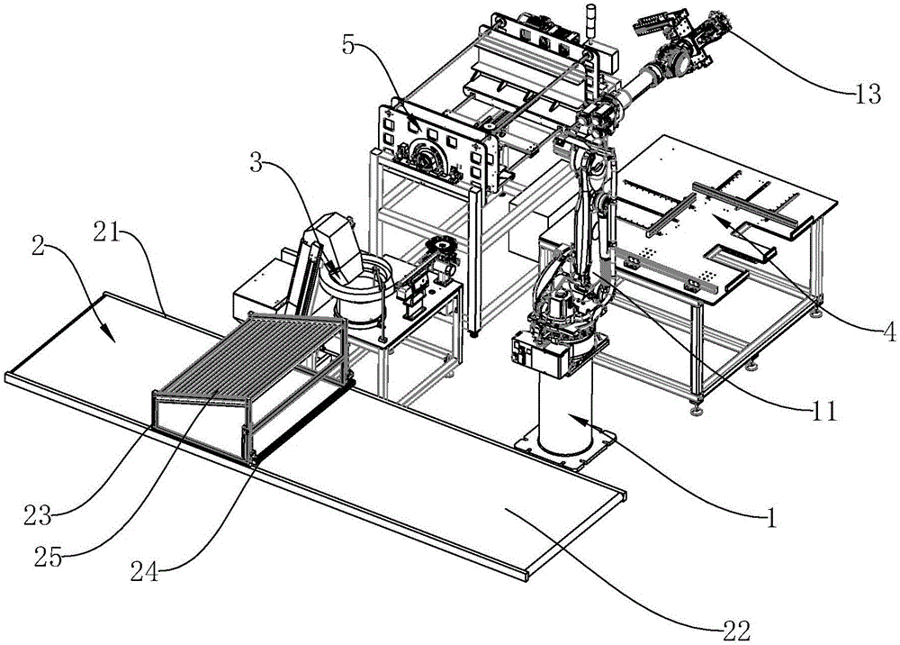
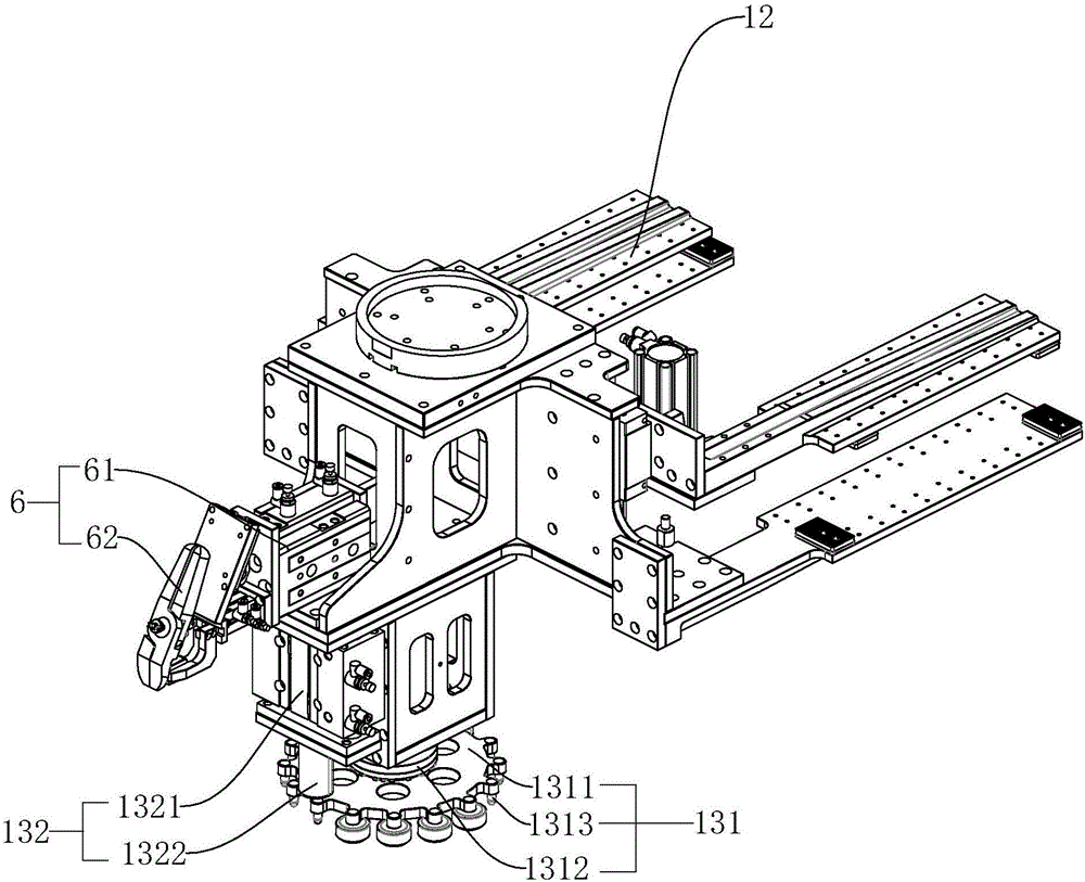
[0032] Embodiment 1: As shown in the figure, an automatic assembly line for plastic pallets includes a manipulator assembly 1. The manipulator assembly 1 consists of a manipulator 11 with six degrees of freedom and a gripper 12 and feet arranged on the manipulator 11. The installation mechanism 13 is composed of;

[0033] A conveying device 2, the conveying device 2 conveys the plastic tray injection-molded by the injection molding machine for gripping by the gripper 12; and conveys the plastic tray with feet installed on both sides transferred by the gripper 12;

[0034] A foot feeding device 3, the foot feeding device 3 provides automatically arranged feet for the foot installation mechanism 13 to obtain;

[0035] A pallet positioning device 4, after the pallet positioning device 4 clamps the plastic pallet provided by the jaws 12, the foot installation mechanism 13 provides the feet and makes the feet installed on the upward surface of the plastic pallet; and

[0036] A tr...

Embodiment 2

[0037] Embodiment 2: As shown in the figure, an automatic assembly line for plastic pallets includes a manipulator assembly 1. The manipulator assembly 1 consists of a manipulator 11 with six degrees of freedom and a gripper 12 and feet arranged on the manipulator 11. The installation mechanism 13 is composed of;

[0038] A conveying device 2, the conveying device 2 conveys the plastic tray injection-molded by the injection molding machine for gripping by the gripper 12; and conveys the plastic tray with feet installed on both sides transferred by the gripper 12;

[0039] A foot feeding device 3, the foot feeding device 3 provides automatically arranged feet for the foot installation mechanism 13 to obtain;

[0040] A pallet positioning device 4, after the pallet positioning device 4 clamps the plastic pallet provided by the jaws 12, the foot installation mechanism 13 provides the feet and makes the feet installed on the upward surface of the plastic pallet; and

[0041] A tr...

Embodiment 3

[0051] Embodiment 3: As shown in the figure, an automatic assembly line for plastic pallets includes a manipulator assembly 1. The manipulator assembly 1 consists of a manipulator 11 with six degrees of freedom, a gripper 12 and a pad set on the manipulator 11. The installation mechanism 13 is composed of;

[0052] A conveying device 2, the conveying device 2 conveys the plastic tray injection-molded by the injection molding machine for gripping by the gripper 12; and conveys the plastic tray with feet installed on both sides transferred by the gripper 12;

[0053] A foot feeding device 3, the foot feeding device 3 provides automatically arranged feet for the foot installation mechanism 13 to obtain;

[0054] A pallet positioning device 4, after the pallet positioning device 4 clamps the plastic pallet provided by the jaws 12, the foot installation mechanism 13 provides the feet and makes the feet installed on the upward surface of the plastic pallet; and

[0055] A tray turnin...


PUM


Abstract

The invention discloses an automatic assembly line of plastic trays. The automatic assembly line comprises a mechanical hand assembly, a conveying device, a pad foot feed device, a tray locating device and a tray turnover device. The mechanical hand assembly is composed of a mechanical arm with six degrees of freedom, a clamping jaw and a pad foot mounting mechanism, wherein the clamping jaw and the pad foot mounting mechanism are arranged on the mechanical arm. The conveying device conveys the plastic trays obtained through injection molding through an injection molding machine so that the plastic trays can be clamped by the clamping jaw, and the conveying device conveys the plastic trays transferred by the clamping jaw, wherein pad feet are mounted on the two faces of each plastic tray. The pad foot feed device provides the pad feet obtained after automatic arrangement so that the pad feet can be acquired by the pad foot mounting mechanism. After the tray locating device clamps the plastic trays provided by the clamping jaw, the pad foot mounting mechanism provides the pad feet, and the pad feet are mounted on the upward surfaces of the plastic trays. The tray locating device clamps the plastic trays provided by the clamping jaw. The automatic assembly line has the beneficial effects that assembly automation is achieved, the work efficiency is improved, and the labor intensity of workers is relieved.

Description

technical field [0001] The invention relates to the field of plastic pallet production, in particular to an automatic assembly line for plastic pallets. Background technique [0002] At present, with the rapid development of the economy, logistics has become an important part of the production process, and a large number of pallets are needed in the logistics and production turnover to facilitate handling and loading and unloading with small forklifts. Plastic pallets have many advantages such as high strength, high bearing capacity and long service life, so they are widely welcomed by people. [0003] The raw material of the plastic tray is generally low-pressure high-density polyethylene, which is injected and molded by the injection molding machine to complete the preliminary production of the plastic tray. However, after the plastic tray is produced from the injection molding machine, it is necessary to install rubber on both sides of the tray. Footsteps can become fini...

Claims


Application Information

Patent Timeline
IPC IPC(8): B29C65/56B29C65/78B29C45/38B29C45/17
CPCB29C45/1769B29C45/382B29C65/56B29C65/7802B29C65/7805
Inventor 施宏豫吴金锐汪雄
Owner 宁波海天智联科技有限公司
Learn More