Charging pile for charging of new energy automobiles

A technology of new energy vehicles and charging piles, applied in electric vehicle charging technology, charging stations, electric vehicles, etc., can solve problems such as leakage, danger, and increased workload of staff, so as to improve reliability and practicability Effect

Inactive Publication Date: 2017-05-31
SHANGHAI SAFEGREEN TECH
View PDF6 Cites 19 Cited by
  • Summary
  • Abstract
  • Description
  • Claims
  • Application Information

AI Technical Summary

Problems solved by technology

[0003] During the working process of the charging pile, the staff needs to pull the charging gun to the position of the electric car to charge the car, but because the charging gun needs to move a long distance, it is generally equipped with a long connecting wire, but due to the connection The wire is too long, which will cause some trouble when retracting it. If it is not retracted, it is easy to be crushed by other cars or staff, and leakage will occur after a long time, causing danger. If it is retracted, but Due to the lack of a good winding mechanism, the workload of the staff is greatly increased and the practicability of the charging pile is reduced; not only that, but in the process of the charging pile working, the working power circuit needs to output a stable working voltage to realize It works stably, but because the working power supply circuit uses conventional voltage-stabilizing transistors for voltage-stabilizing output, and due to the lack of a good feedback detection function, the stability of the charging pile is greatly reduced.

Method used


Image

  • Charging pile for charging of new energy automobiles
  • Charging pile for charging of new energy automobiles
  • Charging pile for charging of new energy automobiles

Examples


Embodiment Construction

[0031] The present invention is described in further detail now in conjunction with accompanying drawing. These drawings are all simplified schematic diagrams, which only illustrate the basic structure of the present invention in a schematic manner, so they only show the configurations related to the present invention.

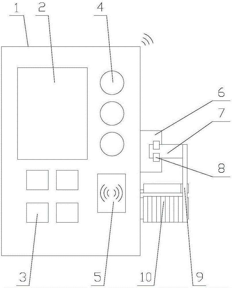
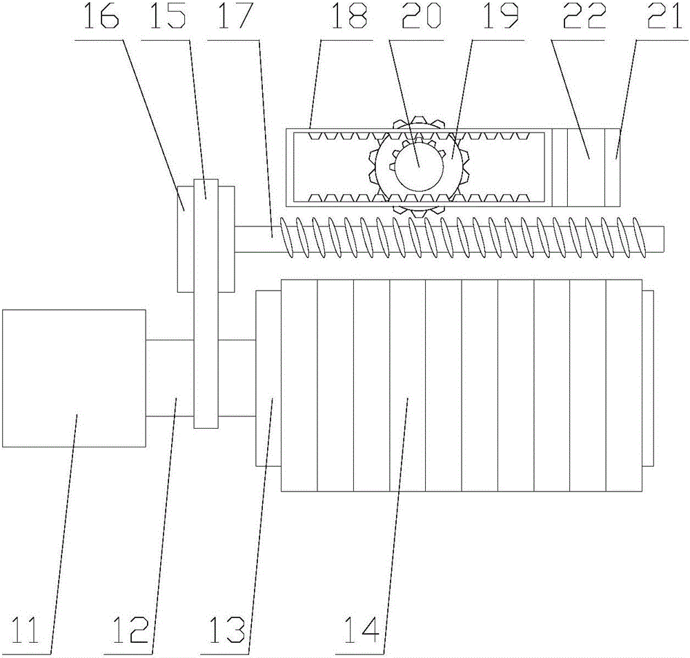
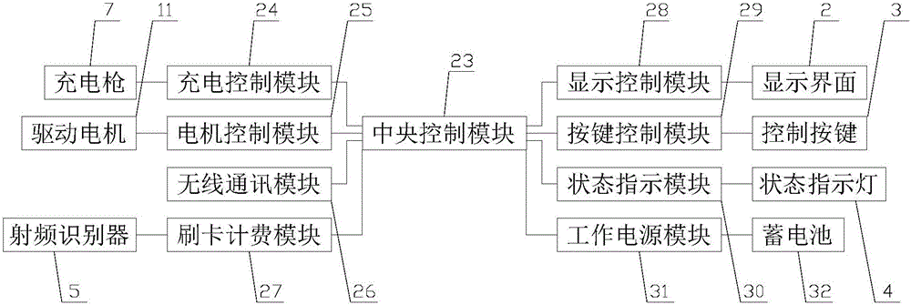
[0032] like Figure 1-Figure 4 As shown, a charging pile for charging new energy vehicles includes a main body 1, a central control mechanism and a charging mechanism, the central control mechanism is arranged inside the main body 1, and the charging mechanism is arranged on one side of the main body 1;

[0033] Among them, the central control mechanism is used to realize the intelligent control of the charging pile; the charging mechanism is used to realize the charging of electric vehicles, etc., and at the same time realize the reliable winding of the wire 9, which improves the reliability of the charging pile.

[0034] The charging mechanism includes a fi...


PUM


Abstract

The invention relates to a charging pile for charging of new energy automobiles. The charging pile comprises a body, a center control mechanism and a charging mechanism. The charging mechanism comprises a fixed socket, a charging gun, a wire and a wire winding mechanism. The wire winding mechanism comprises a driving assembly, a transmission assembly and a wire winding assembly. The transmission assembly comprises a belt wheel, a driven shaft, a transmission gear, a driving gear and a transmission frame. The wire winding assembly comprises a wire frame and a wire winding wheel. A working power module comprises a working power circuit. According to the charging pile for charging of the new energy automobiles, the wire at the position of the charging gun after charging is completed is reliably wound through a limiting mechanism, and therefore the practicality of the charging pile is improved. Thus, in the working power circuit, an integrated circuit acquires and detects input and output voltage in real time, therefore, a triode is controlled to be switched on and off, and the reliability of the charging pile is improved.

Description

technical field [0001] The invention relates to the field of new energy equipment, in particular to a charging pile for charging new energy vehicles. Background technique [0002] The function of the charging pile is similar to the refueling machine in the gas station. It can be fixed on the ground or wall, and installed in public buildings (public buildings, shopping malls, public parking lots, etc.) and residential area parking lots or charging stations. Charge all models of electric vehicles. The input end of the charging pile is directly connected to the AC grid, and the output end is equipped with a charging plug for charging the electric vehicle. Charging piles generally provide two charging methods: conventional charging and fast charging. People can use a specific charging card to swipe the card on the human-computer interaction interface provided by the charging pile to perform corresponding charging methods, charging time, and cost data printing. The display scre...

Claims


Application Information

Patent Timeline
Patent Type & Authority Applications(China)
IPC IPC(8): B60L11/18B65H75/44
CPCB60L53/31B65H75/4405B65H2701/34Y02T10/70Y02T10/7072Y02T90/12Y02T90/14
Inventor 蒙泽喜
Owner SHANGHAI SAFEGREEN TECH
Why Eureka
Try Eureka