
Inertia locking mechanism for seat

A technology of locking mechanism and inertia, which is applied to vehicle seats, movable seats, special positions of vehicles, etc., can solve problems such as insufficient seat strength, and achieve the effect of improving fault tolerance

Active Publication Date: 2017-05-31
YANFENG ADIENT (SHENYANG) SEATING CO LTD
View PDF5 Cites 0 Cited by
  • Summary
  • Abstract
  • Description
  • Claims
  • Application Information

AI Technical Summary

Problems solved by technology

[0005] The problem to be solved by the present invention is to provide an inertial locking mechanism for single-side recliner seats aiming at the contradiction between the cost, weight and safety performance of the current rear seats
The inertia locking mechanism can solve the problem of insufficient strength of the recliner seat on one side in the front and rear impact tests. At the same time, the stopper will not interfere with the folding and use of the seat during normal use. There will be no shaking noise

Method used


Image

  • Inertia locking mechanism for seat
  • Inertia locking mechanism for seat
  • Inertia locking mechanism for seat

Examples


Embodiment 1

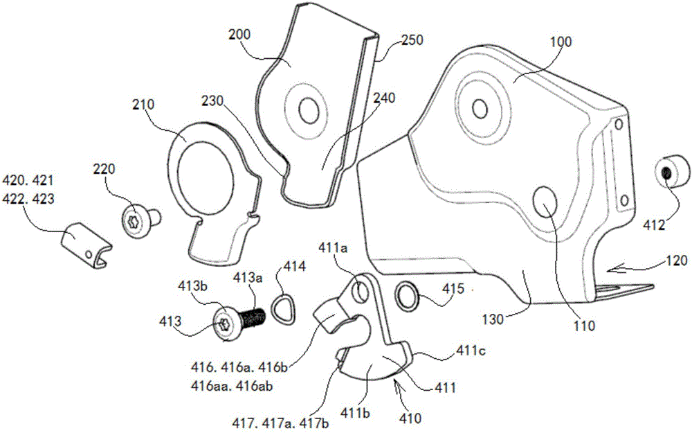
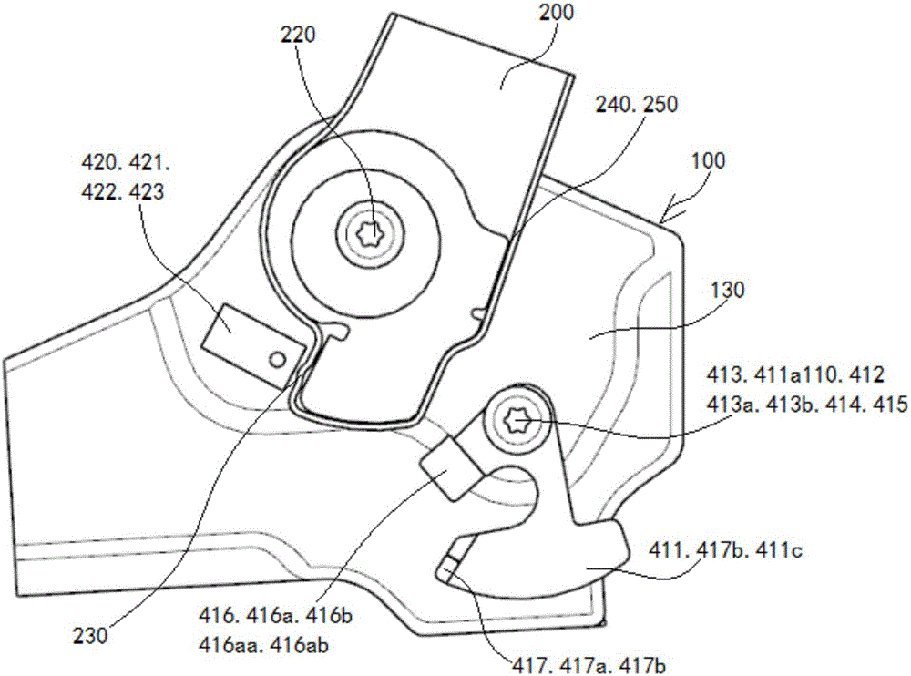
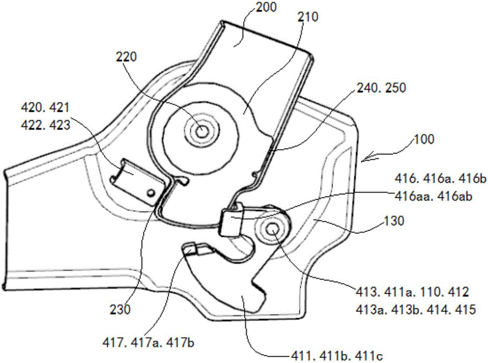
[0057] see figure 1 and Figure 6 to Figure 19 , the inertia locking mechanism shown in the figure is used for the single-side recliner seat in the rear row. The fixed part is the seat cushion side panel 100, the rotating part is the backrest side panel 200, the backrest side panel reinforcement plate 210 and the backrest side panel 200 are welded as a whole, and the backrest side panel 200 is hinged to the seat cushion side panel 100 through the backrest step bolt 220 Above, the backrest side panel 200 turns back and forth around the center of the backrest step bolt 220, driving the seat back to turn back and forth.

[0058] The inertial locking mechanism of this embodiment includes a forward collision inertial locking mechanism assembly 410 and a rear collision stopper 420 . The rear impact block 420 is fixed on the seat cushion side panel 100 and is located at the front side of the lower part of the backrest side panel 200 in the rotation direction.

[0059] see in conju...

Embodiment 2

[0071] see Figure 20 to Figure 34, the inertial locking mechanism shown in the figure is used for rear single-side recliner seats. Its fixed parts include seat cushion side plate 510 and backrest connecting plate 520, and rotating parts include backrest side plate 610 and backrest side plate reinforcing plate 620; the lower part of backrest connecting plate 520 is fixed on the seat cushion side by two back connecting plate fixing bolts 530 On the plate 510, the backrest side panel reinforcing plate 620 and the backrest side panel 610 are welded as a whole, the backrest side panel 610 is hinged on the backrest connecting plate 520 through the backrest step bolt 630, and the backrest side panel 610 is turned back and forth around the center of the backrest step bolt 630 , to drive the seat back to flip back and forth.

[0072] The inertia locking mechanism includes a rear impact inertia locking mechanism assembly 700, which is hinged on the seat cushion side panel 510 and is l...


PUM


Abstract

The invention discloses an inertia locking mechanism for a seat. The inertia locking mechanism is characterized by comprising an inertia locking mechanism body which is used in a combined structure of a rotating part and a fixed part in the seat, wherein the rotating part is hinged to the fixed part; the inertia locking mechanism body is installed on the fixed part. During collision, the inertia locking mechanism body locks up the rotating part by the aid of inertia, and on normal condition, the inertia locking mechanism body does not lock up the rotating part without affecting rotation of the rotating part. The inertia locking mechanism can solve the problem that the one-sided medium and low strength angle-adjuster seat is insufficient in strength in front-back collision test, a stop piece cannot interfere turnover and use of the seat in the normal use process, and the inertia retaining piece cannot cause shaking and abnormal noise. The cost of the inertia locking mechanism is only 25%-30% of that of the conventional scheme.

Description

technical field [0001] The invention relates to the technical field of seats, in particular to an inertia locking mechanism for a seat. Background technique [0002] With the continuous improvement of society's requirements for automobile safety, many OEMs have put forward safety requirements for rear seats in front and rear collisions. Under this background, many rear seats use double-sided recliners to increase The strength of the seat is expected to obtain better performance in the crash test. However, the cost and weight of the double-sided recliner are relatively high, and the unlocking force is also relatively large, while the strength of the single-sided recliner cannot meet the requirements of the rear seat front and rear impact test, so a new seat structure is urgently needed. On the one hand Low cost, light weight, comfortable operation, on the other hand, it can also meet the requirements of OEMs for front and rear crash tests. [0003] In the traditional soluti...

Claims


Application Information

Patent Timeline
Patent Type & Authority Applications(China)
IPC IPC(8): B60N2/44B60N2/22B60N2/90
CPCB60N2/22B60N2/919B60N2002/952
Inventor 杨野龙勇张辉居成效
Owner YANFENG ADIENT (SHENYANG) SEATING CO LTD
Learn More