
Variable speed device for crawler harvester

A technology of transmission and harvester, applied in steering mechanism, mechanical equipment, belt/chain/gear, etc., can solve the problems of unsuitability for paddy field operation, low steering efficiency, easy sinking and slipping, etc.

Inactive Publication Date: 2017-05-31
HUNAN AGRICULTURAL UNIV
View PDF5 Cites 6 Cited by
  • Summary
  • Abstract
  • Description
  • Claims
  • Application Information

AI Technical Summary

Problems solved by technology

[0002] Due to the large water demand of rice during the whole growth process, long-term water storage in paddy fields leads to soft soil and poor bearing capacity. Wheeled operating machinery is prone to sinking and slipping after leaving the field, which is not suitable for paddy field operations; due to the large ground area of ​​crawler operating machinery, the unit The ground pressure is small, the subsidence is small during field operation, the damage to the paddy field is small, and the paddy field has strong adaptability
However, the existing crawler harvesters usually use the tooth embedded clutch to steer. When turning, the power on the steering side is separated or braked, so that the speed of the inner track is lower than the speed of the outer track to realize the steering. , the steering is more accurate, and the damage to the farmland is small; when the steering is at a large angle (such as a U-turn at the head of the field), the track harvester rotates around the center of the inner track because the inner track stops moving, resulting in the accumulation of mud around the turn and damage to the farmland. At the same time, because one side of the track loses power when turning, the turning efficiency is low

Method used


Image

  • Variable speed device for crawler harvester
  • Variable speed device for crawler harvester
  • Variable speed device for crawler harvester

Examples


Embodiment Construction

[0041] In order to make the technical means, creative features, goals and effects achieved by the present invention easy to understand, the present invention will be further described below in conjunction with specific illustrations.

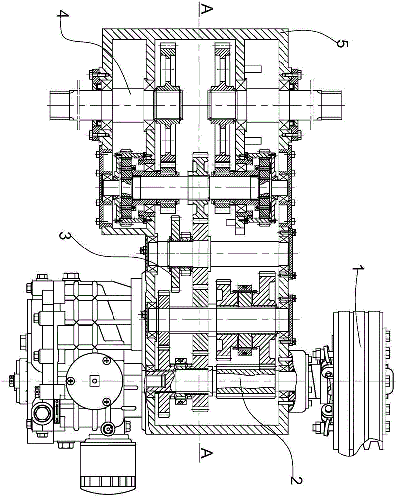
[0042] see figure 1 A transmission for a crawler harvester, comprising a clutch assembly 1, a speed change assembly 2, a steering power transmission assembly 3, a track wheel drive assembly 4 and a box assembly 5, wherein the speed change assembly 2, the steering power The transmission assembly 3 and the track wheel drive assembly 4 are respectively installed in the box assembly 5, the clutch assembly 1 is connected with the transmission assembly 2, the transmission assembly 2 is connected with the steering power transmission assembly 3, and the steering power transmission assembly 3 is connected with the track wheel drive assembly 4, and the specific structure of each mechanism is as follows:

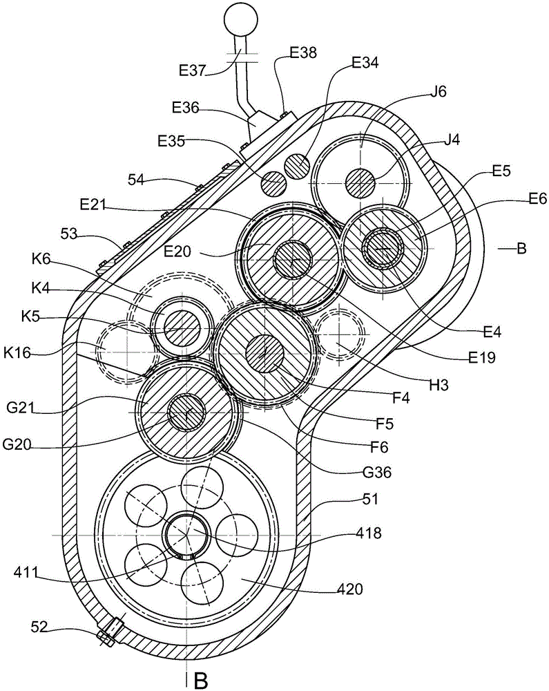
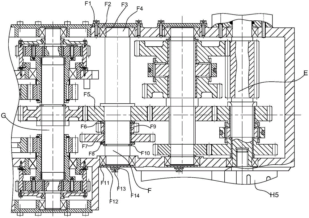
[0043] see Figure 2 to Figure 8 As shown, the t...


PUM


Abstract

The invention discloses a variable speed device for a crawler harvester. The variable speed device comprises a clutch assembly, a variable speed assembly, a steering power transmission assembly, a crawler wheel drive assembly and a box body assembly, wherein the variable speed assembly, the steering power transmission assembly, and the crawler wheel drive assembly are respectively mounted on the inner side of the box body assembly, and the clutch assembly and the variable speed assembly are connected, the variable speed assembly and the steering power transmission assembly are connected, and the steering power transmission assembly and the crawler wheel drive assembly are connected. A hydrostatic infinitely variable speed device is adopted to drive the variable speed assembly and is combined with a planetary gear transmission mechanism after the speed retardation, the crawler drive force is not stopped at the time of steering, so that the speed of the steering angle and the rotary speed of the hydrostatic infinitely variable speed device have a certain proportional relation, the control of the steering direction and the angle speed is determined by the steering direction and the rotary speed of the hydrostatic infinitely variable speed device, the accuracy of the steering direction is good, and the efficiency of the steering direction is high, the sludge and piles formed in the steering of the crawler harvester are reduced, and the flatness of a rice field is increased.

Description

technical field [0001] The invention relates to the technical field of crawler equipment power transmission, in particular to a transmission for a crawler harvester. Background technique [0002] Due to the large water demand of rice during the whole growth process, long-term water storage in paddy fields leads to soft soil and poor bearing capacity. Wheeled operation machinery is easy to sink and slip after leaving the field, which is not suitable for paddy field operations; The grounding pressure is small, the subsidence is small during field operation, the damage to the paddy field is small, and the paddy field has strong adaptability. However, the existing crawler harvesters usually use the tooth embedded clutch to steer. When turning, the power on the steering side is separated or braked, so that the speed of the inner track is lower than the speed of the outer track to realize the steering. , the steering is more accurate, and the damage to the farmland is small; when...

Claims


Application Information

Patent Timeline
Patent Type & Authority Applications(China)
IPC IPC(8): B62D11/10B60K17/04F16H37/06F16H57/08F16H57/023
CPCB60K17/04B62D11/10F16H37/065F16H57/023F16H57/082
Inventor 孙松林肖名涛熊力魏刚刘欣
Owner HUNAN AGRICULTURAL UNIV
Learn More