Tank top discharge device and installation method

An installation method and ejection technology, which are applied in the field of tank top discharge device and tank container, can solve the problems of inability to install large-sized valves and small distances, so as to solve the problem of inability to install higher top discharge valves and simple structure. , the effect of making convenient

Active Publication Date: 2019-03-19
NANTONG TANK CONTAINER CO LTD
View PDF11 Cites 0 Cited by
  • Summary
  • Abstract
  • Description
  • Claims
  • Application Information

AI Technical Summary

Problems solved by technology

The unloading methods mainly include top discharge and bottom discharge. For tank containers with top discharge, the top discharge structure of large-volume tanks generally includes a butterfly valve and a general sinking flange. The size of the butterfly valve is 3 inches, and the outlet of the drain tank is just placed on the top of the tank, but the distance from the top of the large-volume tank to the top of the tank frame is relatively small, and it is impossible to install large-sized and taller valves, such as 5-inch ball valves

Method used


Image

  • Tank top discharge device and installation method
  • Tank top discharge device and installation method

Examples


Embodiment Construction

[0017] In order to make the purpose, technical solutions and advantages of the embodiments of the present invention clearer, the technical solutions in the embodiments of the present invention will be clearly and completely described below. Obviously, the described embodiments are part of the embodiments of the present invention, not all of them. the embodiment. Elements and features described in one embodiment of the present invention may be combined with elements and features shown in one or more other embodiments. It should be noted that representation and description of components and processes that are not related to the present invention and that are known to those of ordinary skill in the art are omitted from the description for the purpose of clarity. Based on the embodiments of the present invention, all other embodiments obtained by persons of ordinary skill in the art without making creative efforts belong to the protection scope of the present invention.

[0018] ...


PUM


Abstract

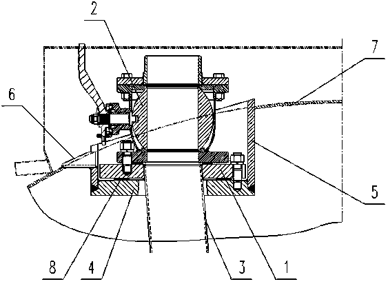
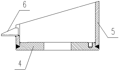
The invention discloses a tank box top discharge device. The tank box top discharge device comprises a sunken flange arranged in a tank body. The upper portion of the sunken flange is connected with an adapter flange through a bolt. A ball valve is connected to the adapter flange through a bolt, an inclined siphon is arranged below the sunken flange and the adapter flange, and the ball valve communicates with the inclined siphon. The sunken flange comprises a flange body, a shell ring and a drain groove. The flange body and the shell ring are connected in a welded manner, and the drain groove stretches out of the tank body. An installing method includes the steps that the ball valve is pre-assembled on the adapter flange, the adapter flange is assembled on the sunken flange, and the highest utilization rate of space is achieved under the condition of guaranteeing normal assembly. The assembly requirement of a large-size top discharge ball valve of a large-capacity tank box is met by mainly adopting the novel sunken flange structure and the novel adapter flange assembly. The tank box top discharge device has the beneficial effects that the structure is simple, manufacturing is convenient, use is reliable, and the problem that a high top discharge valve cannot be installed on the large-capacity tank box is solved.

Description

Technical field: [0001] The invention relates to the field of mobile liquid transportation equipment, and is mainly used in the tank container industry, in particular to a tank top discharge device and an installation method. Background technique: [0002] Tank containers are widely used in the logistics and transportation industry due to their advantages of safety, speed and intermodal transport. The unloading methods mainly include top discharge and bottom discharge. For tank containers with top discharge, the top discharge structure of large-volume tanks generally includes a butterfly valve and a general sinking flange. The size of the butterfly valve is 3 inches, and the outlet of the drain tank is just placed on the top of the tank, but the distance from the top of the large-volume tank to the top of the tank frame is relatively small, and it is impossible to install large-sized and tall valves, such as 5-inch ball valves . Invention content: [0003] The object of ...

Claims


Application Information

Patent Timeline
Patent Type & Authority Patents(China)
IPC IPC(8): B65D90/54
CPCB65D90/54
Inventor 顾洪飞崔杨益周元网
Owner NANTONG TANK CONTAINER CO LTD
Why Eureka
Try Eureka