Control system of fabric spreading device

A control system and cloth spreading technology, applied in the field of sewing machines, can solve the problems of time-consuming and laborious, inconvenient to suspend the machine, machine collision, etc., to avoid wasting time and manpower.

Active Publication Date: 2017-05-31
BULLMER ELECTROMECHANICAL TECH
View PDF6 Cites 2 Cited by
  • Summary
  • Abstract
  • Description
  • Claims
  • Application Information

AI Technical Summary

Problems solved by technology

At present, the length of the platen in garment factories is generally 40-50 meters. If the machine stops at the starting point and the operator works at the end point, when the operator needs to shut down the spreading machine, he has to walk to one end of the platen. Then return to the other end of the platen to adjust the fabric, and then go back to the spreader to start the spreader, so that the employees have to go back and forth twice to complete the above actions, which is very time-consuming and laborious
Moreover, the machine was in motion for a period of time, and the fastest speed was about 100m / min, so it was not only inconvenient for the operator to stop the machine, but sometimes there was a danger of being hit by the machine

Method used


Image

  • Control system of fabric spreading device
  • Control system of fabric spreading device

Examples


Embodiment Construction

[0018] Specific embodiments of the present invention will be described in further detail below based on the accompanying drawings. It should be understood that the specific embodiments described here are only examples, and are not intended to limit the protection scope of the present invention.

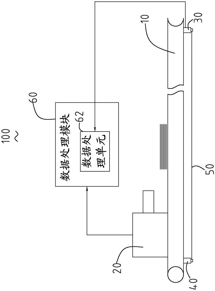
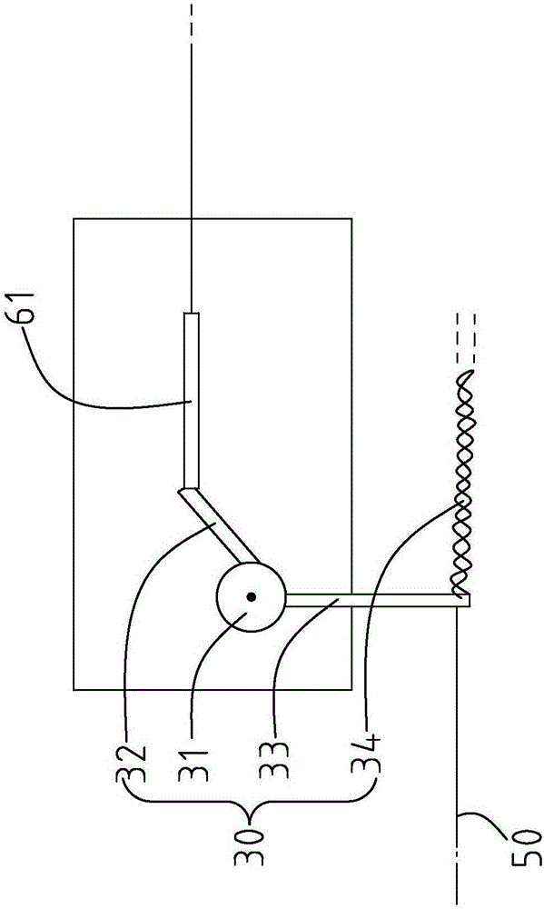
[0019] see figure 1 with figure 2 , which is a structural schematic diagram of a control system 100 of a spreading device provided by the present invention. The control system 100 of the spreading device comprises a spreading table 10, a spreading machine 20 arranged on the spreading table 10, a limit switch 30 arranged at one end of the spreading table 10, a A cable fixed end 40 arranged at the other end of the spreading table 10 relative to the limit switch 30, a cable 50 arranged between the limit switch 30 and the cable fixed end 40, and a cable fixed by The data processing module 60 controlled by the limit switch 30 is provided with the above-mentioned structure of the limit ...


PUM

PropertyMeasurementUnit
lengthaaaaaaaaaa

Abstract

The invention relates to a control system of a fabric spreading device. The control system comprises a fabric spreading machine, a limit switch, an inhaul cable and a data processing module, wherein the limit switch comprises a wheel disc, a switch blade, a pull rod and an elastic part; the pull rod and the switch blade are arranged in the radial direction of the wheel disc in a deviated manner; the pull force direction of the inhaul cable is opposite to the restoring force direction of the elastic part; the data processing module comprises a contact and a data processing unit, the on and off of the contact are controlled by the switch blade, and the data processing unit receives the triggering signal of the contact; the data processing unit controls the fabric spreading machine to switch on and switch off according the triggering signal of the contact. The control system has the advantages that by the control system, an operator can pull the inhaul cable to switch on and switch off the fabric spreading machine, the operator does not need to walk back and forth beside a fabric spreading table of 30-50 meters, and time and manpower waste can be avoided.

Description

technical field [0001] The invention relates to the field of sewing machines, in particular to a control system for a spreading device. Background technique [0002] The fabric spreading device is a machine designed to cut according to a uniform size, so that multiple layers of fabric can be laid on the table together and moved. For example, the patent No. is 201110275908.X, and the patent application for a spreading machine with the patent name discloses a spreading device. The spreading machine includes a table, rails arranged on both sides of the table, a body of the spreading machine traveling on the rail, and a driving mechanism. However, during the actual operation of the spreading machine, the machine will be suspended at any time to make corresponding adjustments according to the situation. The devices for controlling the running state of the spreading machine are all arranged on the spreading machine body. When the spreader needs to be shut down, it is necessary ...

Claims


Application Information

Patent Timeline
Patent Type & Authority Applications(China)
IPC IPC(8): B65H47/00B65H43/00
CPCB65H43/00B65H47/00B65H2557/25B65H2557/30
Inventor 肖科科余建军
Owner BULLMER ELECTROMECHANICAL TECH
Why Eureka
Try Eureka