Variable-stroke high-and-low-beam travelling crane for crane machine room

A crane and gantry crane technology, which is applied in the direction of cranes, load blocks, load suspension components, etc., can solve problems such as collisions, increased activity space in the machine room, and limited space on the ground layout of the machine room, so as to avoid interference, facilitate operation, and increase the lifting capacity. big effect

Inactive Publication Date: 2017-05-31
QINGDAO HAIXI HEAVY DUTY MASCH CO LTD
View PDF8 Cites 2 Cited by
  • Summary
  • Abstract
  • Description
  • Claims
  • Application Information

AI Technical Summary

Problems solved by technology

For the first solution, other lifting equipment must be borrowed, and due to the limitation of the size of the skylight, it is difficult for the hook of the lifting equipment to reach a position far from the skylight; for the second solution, due to the limitation of the turning radius of the turntable tail, The layout space is limited, and opening a hanging hole that can pass through large equipment such as reducers will inevitably increase the activity space in the machine room, and the bottom of the machine room often has structures such as round platforms and door frames, which are easy to collide with during the lifting process of equipment

Method used


Image

  • Variable-stroke high-and-low-beam travelling crane for crane machine room
  • Variable-stroke high-and-low-beam travelling crane for crane machine room
  • Variable-stroke high-and-low-beam travelling crane for crane machine room

Examples


Embodiment Construction

[0029] The present invention will be further described below in conjunction with the accompanying drawings and embodiments.

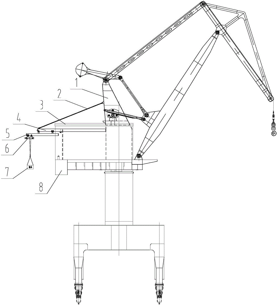
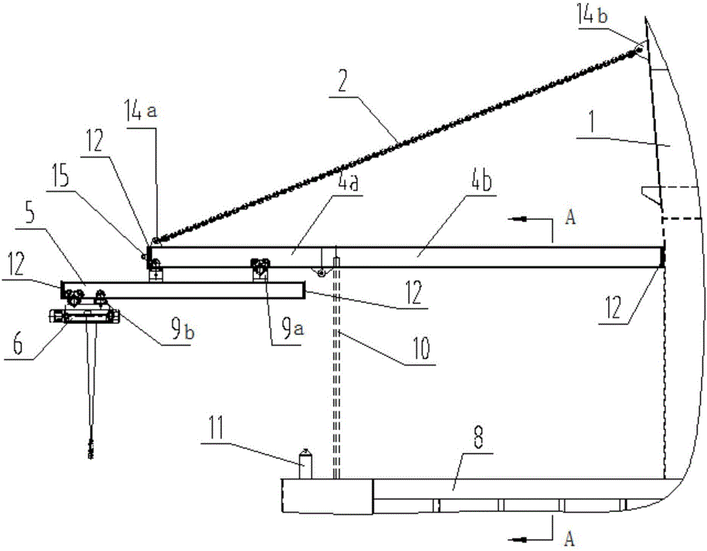
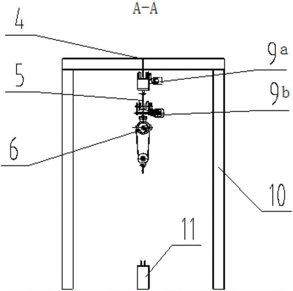
[0030] Such as Figure 1-6 As shown, a variable stroke high and low beam crane for a crane machine room includes an upper track beam 4, a lower track beam 5, an electric hoist 6 and a walking block, wherein there are multiple walking blocks, which are respectively the first traveling block 9a and the second Two walking blocks 9b, and the lower track beam 5 is located under the upper track beam 4, and the upper track beam 4 and the lower track beam 5 can be slidably matched by the first walking block 9a, and the electric hoist 6 is located under the lower track beam 5, And the lower track beam 5 and the electric hoist 6 can slide and cooperate through the second traveling block 9b, that is, the lower track beam 5 runs on the upper track beam 4 through the first traveling block 9a, and the electric hoist 6 passes through the second traveling block 9b Run...


PUM


Abstract

The invention discloses a variable-stroke high-and-low-beam travelling crane for a crane machine room. The variable-stroke high-and-low-beam travelling crane comprises an upper track beam, a lower track beam, an electric hoist and a plurality of running blocks, wherein the plurality of running blocks include first running blocks and second running blocks; the upper track beam and the lower track beam are in sliding fit through the first running blocks; the lower track beam and the electric hoist are in sliding fit through the second running blocks; the upper track beam comprises a movable beam and a fixed beam; the fixed beam is located in the machine room; the machine room is located on a turntable of a gate seat crane; the right end of the fixed beam is fixed on an upright post; the upright post is arranged on the turntable of the gate seat crane; the left end of the fixed beam is supported by a support beam located on the turntable and connected with the right end of the movable beam through a hinge; and the left end of the movable beam extends out of the machine room and is detachably connected with the upright post of the gate seat crane through a digging line. The travelling crane is convenient to operate and high in loading capacity, has a large outreach and can be completely fixed in the machine room when not used.

Description

technical field [0001] The invention belongs to the technical field of hoisting equipment, and in particular relates to a variable stroke high and low beam crane used in a crane machine room. Background technique [0002] The hoisting mechanism, luffing mechanism and slewing mechanism of the crane are usually installed in the machine room, and the machine room is higher than the ground. Or reducer and other equipment for maintenance, and the weight of motor or reducer and other equipment is relatively large, they must be hoisted to the ground with special lifting equipment for maintenance. At present, two schemes are usually adopted: one is to set up a skylight on the roof of the machine room, and use large lifting equipment to lift the equipment to be repaired from the skylight; The hoist lifts the equipment from the lifting hole to the ground. For the first solution, other lifting equipment must be borrowed, and due to the limitation of the size of the skylight, it is di...

Claims


Application Information

Patent Timeline
IPC IPC(8): B66C11/10B66C23/16B66C23/62
CPCB66C11/10B66C23/16B66C23/62
Inventor 梁强张金营王焕朋王义凡赵增林
Owner QINGDAO HAIXI HEAVY DUTY MASCH CO LTD
Why Eureka
Try Eureka