Method and device for controlling oxygen concentration of optical fiber curing oven

A technology of oxygen concentration and control method, applied in the direction of ratio control, control/regulation system, non-electric variable control, etc., can solve the problems of inability to monitor oxygen concentration and multi-range adjustment, so as to improve the curing effect, increase the oxygen content, The effect of increasing the oxygen concentration

Inactive Publication Date: 2017-05-31
HANGZHOU FUTONG COMM TECH CO LTD
View PDF8 Cites 3 Cited by
  • Summary
  • Abstract
  • Description
  • Claims
  • Application Information

AI Technical Summary

Problems solved by technology

It solves the problem that the existing technology cannot monitor the oxygen concentration in real time and cannot adjust the oxygen concentration in multiple ranges

Method used


Image

  • Method and device for controlling oxygen concentration of optical fiber curing oven

Examples


Embodiment 1

[0044] In order to control the oxygen concentration in the optical fiber curing furnace, this embodiment discloses a method for controlling the oxygen concentration in the optical fiber curing furnace, including:

[0045] Connect the first nitrogen pipe to the upper joint of the optical fiber curing furnace, feed nitrogen into the first nitrogen pipe, and discharge the nitrogen gas fed into the first nitrogen pipe from the upper end of the upper joint;

[0046] Connect the second nitrogen pipe to the lower joint of the optical fiber curing furnace, feed nitrogen into the second nitrogen pipe, and discharge the nitrogen gas fed into the second nitrogen pipe from the lower end of the lower joint;

[0047] Connect the third nitrogen pipe to one of the joints of the optical fiber curing furnace, connect the exhaust pipe to the other joint, feed nitrogen into the third nitrogen pipe, and make the nitrogen fed into the third nitrogen pipe flow from one end of the quartz tube to the ...

Embodiment 2

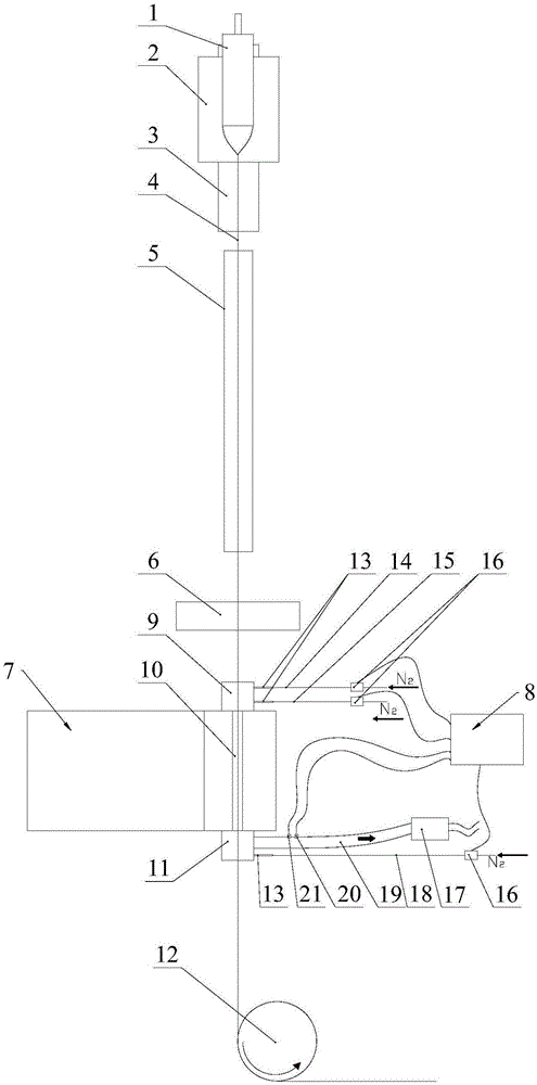
[0057] Such as figure 1 As shown, the optical fiber preform 1 is melted after being heated at a high temperature of 2000-2200°C in the drawing furnace 2. After coming out of the drawing furnace 2, it is annealed through the annealing tube 3. At this time, the temperature is about 900-1200°C, and then passes through the cooling tube 5. Lower the temperature until the process temperature required for coating is 30-80°C. After the optical fiber 4 is cooled, it enters the coating system 6 for coating coating. After coming out of the coating system 6, the surface of the optical fiber 4 will be coated with a liquid coating, which needs to enter the optical fiber curing furnace 7 for curing. According to the difference in process and line speed, 5 to 8 curing furnaces are required, and the optical fiber 4 is collected after being pulled by the pulling device 12 after being cured.

[0058] In order to control the oxygen concentration in the optical fiber curing furnace 7, this embodi...


PUM


Abstract

The application discloses a method and a device for controlling an oxygen concentration of an optical fiber curing oven, wherein the device comprises a first nitrogen tube, a second nitrogen tube, a third nitrogen tube and a gas exhausting tube, three flow meters, a wind speed measuring instrument, an oxygen concentration measuring instrument and a controller, wherein the first nitrogen tube is communicated with an upper joint; the second nitrogen tube is communicated with a lower joint; the third nitrogen tube and the gas exhausting tube are arranged on the two joints respectively; the three flow meters are arranged on the corresponding nitrogen tubes respectively; the wind speed measuring instrument is used for measuring the flow speed of a gas in the gas exhausting tube; the oxygen concentration measuring instrument is used for measuring the concentration of oxygen in the gas exhausting tube; the controller is electrically connected with the three flow meters, a downdraught fan, the wind speed measuring instrument and the oxygen concentration measuring instrument, and is used for controlling each flow meter and the downdraught fan to work according to signals fed back by the oxygen concentration measuring instrument and the wind speed measuring instrument. By using the method and the device, the oxygen concentration can be automatically detected; each flow meter and the downdraught fan can be controlled to work accruing to the oxygen concentration; thus, the oxygen concentration in a quartz tube is enabled to be in a set range.

Description

technical field [0001] The invention relates to optical fiber production equipment, in particular to a method and device for controlling the oxygen concentration of an optical fiber curing furnace. Background technique [0002] The optical fiber structure mainly includes a core, a cladding, a primary coating and a secondary coating. During the production process, after the coating is clad, it needs to be cured by a UV curing oven. The size of the curing strength directly affects the performance of the optical fiber. If the curing is too low, there will be abnormal appearances such as twill, shadows, stickiness, and coloring, which will affect the normal use of the fiber and cause losses; on the contrary, if the curing is too high. It will cause the optical fiber to become yellow, the stripping force is too large, and the coloring and fading of the optical cable will be abnormal. [0003] The oxygen concentration of the UV curing furnace is one of the main factors affecting ...

Claims


Application Information

Patent Timeline
Patent Type & Authority Applications(China)
IPC IPC(8): C03C25/12G05D11/13
CPCC03C25/12G05D11/139
Inventor 胡涛涛陆健红傅志君郭建良乐成军周杭明
Owner HANGZHOU FUTONG COMM TECH CO LTD
Why Eureka
Try Eureka