
A system and method for improving crude oil dehydration efficiency in a combined station

A technology of crude oil dehydration and combined station, which is applied in the fields of hydrocarbon oil dehydration/demulsification, hydrocarbon oil treatment, petroleum industry, etc. It can solve the problems of excessive water content in purified oil and the entry of purified oil into three-phase separators, etc., and achieve the improvement of digital management level , Improve crude oil dehydration efficiency, reduce labor intensity and the effect of combined station operating costs

Active Publication Date: 2019-03-12
PETROCHINA CO LTD
View PDF3 Cites 0 Cited by
  • Summary
  • Abstract
  • Description
  • Claims
  • Application Information

AI Technical Summary

Problems solved by technology

[0005] In order to overcome the problem in the above-mentioned prior art that some unqualified purified oil enters the purified oil tank due to abnormal dehydration of the three-phase separator within the interval of manual sampling of the purified oil at the outlet of the three-phase separator, causing the water content of all purified oil in the purified oil tank to exceed the standard, The purpose of the present invention is to propose a dehydration system and method for improving the crude oil dehydration efficiency of the combined station

Method used


Image

  • A system and method for improving crude oil dehydration efficiency in a combined station
  • A system and method for improving crude oil dehydration efficiency in a combined station
  • A system and method for improving crude oil dehydration efficiency in a combined station

Examples


Embodiment 1

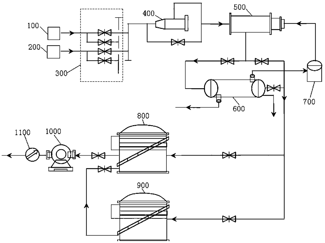
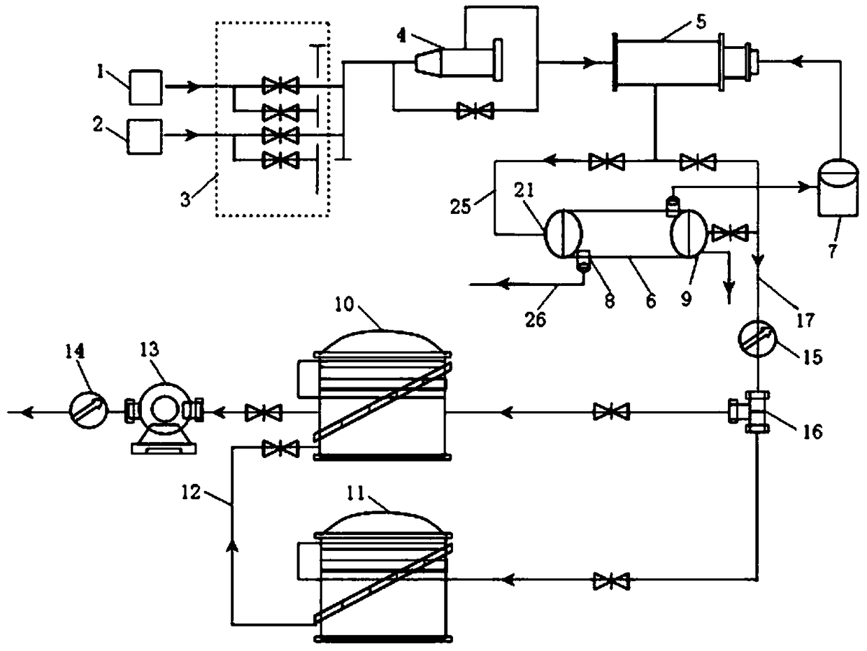
[0027] like figure 2 As shown, an embodiment of the present invention provides a system for improving the dehydration efficiency of crude oil in a combined station, including an oil intake point, a main unit 3, a ball collecting device 4, a heating furnace 5, and a three-phase separator connected in sequence along the crude oil flow direction. 6. The three-phase separator 6 is connected to the purified oil outlet line 17. The purified oil outlet line 17 is provided with a water content monitor 15 and a solenoid valve 16 in turn along the flow direction of the crude oil. The water content monitor 15 and the solenoid valve 16 A controller is connected through a wire; the solenoid valve 16 is connected to a purification oil tank 10 and a sedimentation tank 11 respectively through a wire connection, and the sedimentation tank 11 is connected to the purification oil tank 10 through an overflow line 12, and the purified oil The tank 10 is connected to an external pump 13, and the o...

Embodiment 2

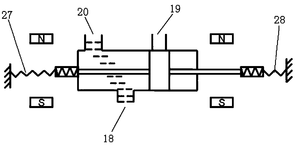
[0032] On the basis of Example 1, as Figures 2 to 4 As shown, the solenoid valve 16 is a three-position three-way solenoid valve, and the circuit control of the three-position three-way solenoid valve is more convenient.

[0033] like Figures 3 to 5As shown, the solenoid valve 16 has an inflow port 18, a first outflow port 19, and a second outflow port 20. The inflow port 18 is connected to the water content monitor 15 through a purified oil outlet line 17, and the first outflow port 19 passes through The pipeline is connected to the purification oil tank 10 , and the second outflow port 20 is connected to the settling tank 11 through the pipeline.

[0034] like image 3 As shown, the left coil 27 of the solenoid valve 16 is energized, and the second outflow port 20 is opened; such as Figure 5 As shown, the right coil 28 of the solenoid valve 16 is energized and the first outflow port 19 is open. When the left coil 27 and the right coil 28 of the solenoid valve 16 are d...

Embodiment 3

[0036] On the basis of Example 1, as figure 2 As shown, the three-phase separator 6 is provided with a water-containing crude oil inlet 21, a sludge outlet 8, a gas-liquid outlet, a produced water outlet 9, and a water-containing crude oil outlet; the water-containing crude oil inlet 21 is connected to one end of the water-containing crude oil pipeline 25, The other end of the water-containing crude oil pipeline 25 is connected to the heating furnace 5 . The water-containing crude oil outlet is connected to one end of the purified oil outlet pipeline 17 , and the other end of the purified oil outlet pipeline 17 is connected to the water content monitor 15 . The sludge outlet 8 is connected to a sewage pipe 26 , and the sewage pipe discharges the sewage separated by the three-phase separator 6 . The gas-liquid outlet is connected to the gas-liquid separator 7 through a pipeline, and the gas-liquid separator 7 communicates with the heating furnace 5, and the separated associat...


PUM


Abstract

The invention discloses a system for improving the crude oil dehydration efficiency of a multi-purpose station. The system comprises a three-phase separator, wherein the three-phase separator is connected with a purified oil outlet line; the purified oil outlet line is sequentially provided with a water content monitor and an electromagnetic valve along the flow direction of crude oil; the water content monitor and the electromagnetic valve are connected with a controller; the electromagnetic valve is connected with a purification tank and a settling tank; the settling tank is connected with the purification tank through an overflow pipe; the purification tank is connected with an efflux pump; an outlet end of the efflux pump is connected with an export flow meter; the moisture content monitor monitors the moisture content of the purified oil at a watered oil outlet of the three-phase separator and transmits the monitored moisture content of the purified oil to the controller; and the controller judges and then controls the electromagnetic valve to be switched and conducted between the purification tank and the settling tank. The water content monitor and the electromagnetic valve are arranged on the purified oil outlet line, the moisture content of the purified oil is continuously collected, data analysis of limited time is carried out and then the electromagnetic valve is controlled, so that the crude oil dehydration efficiency is improved.

Description

technical field [0001] The invention relates to the technical field of oil and gas gathering and transportation in oil fields, in particular to a system and method for improving the dehydration efficiency of crude oil in a combined station. Background technique [0002] In recent years, the ground construction of many oilfields has been closely combined with the geological conditions, development methods, physical properties of the produced materials, and topographical conditions, etc., and implemented the "cluster well group single-pipe unheated oil collection, oil and gas mixed transportation, and three-phase separator closed dehydration". It embodies the technical characteristics of "single, short, simple, small and string", and forms a new surface construction mode suitable for the development of ultra-low permeability reservoirs. [0003] According to the current surface process flow, the joint station mainly undertakes tasks such as crude oil heating, dehydration, puri...

Claims


Application Information

Patent Timeline
Patent Type & Authority Patents(China)
IPC IPC(8): C10G33/00
CPCC10G33/00C10G2300/10
Inventor 赵晓龙罗聪英魏小林张春涛于世春李明江黄天虎程世东于洋
Owner PETROCHINA CO LTD
Learn More