
An operating platform device for laser cladding

An operation platform, laser cladding technology, applied in metal material coating process, coating, etc., can solve the problems of affecting the forming effect, impact, powder splashing, etc., and achieve the improvement of defect problems, convenient and simple operation, and simple equipment relationship Effect

Active Publication Date: 2019-07-09
NORTHEASTERN UNIV LIAONING
View PDF11 Cites 0 Cited by
  • Summary
  • Abstract
  • Description
  • Claims
  • Application Information

AI Technical Summary

Problems solved by technology

[0013] 1. During the cladding process, the cladding working platform cannot be moved. Only by moving the position of the laser head to find the origin position of cladding to start working. This adjustment operation needs to adjust the position of the laser head through the handle of the robot, which needs to be aimed with the naked eye Position and then perform origin calibration. If the operation is improper, the laser head will hit the processing operation plane and damage the laser head.
In addition, due to the limitations of the equipment, if it is necessary to clad the workpiece at a certain angle to the horizontal direction, the cladding operation process will not be possible due to the absence of supporting equipment;
[0014] 2. The temperature of laser cladding is generally about 1000°C. When the number of cladding layers is small, the temperature dissipates quickly. As the layer thickness gradually increases, the temperature and heat accumulation phenomenon gradually becomes serious, which leads to the upper part of the workpiece The temperature and heat accumulation are high, and the "collapse" phenomenon will appear during the cladding process, which will affect the molding effect;
[0015] 3. When the powder feeding amount and scanning speed reach a certain value, the powder ejected by the laser head is faster and the powder amount is relatively large. Unable to collect back, a lot of powder is wasted

Method used


Image

  • An operating platform device for laser cladding
  • An operating platform device for laser cladding
  • An operating platform device for laser cladding

Examples


Embodiment Construction

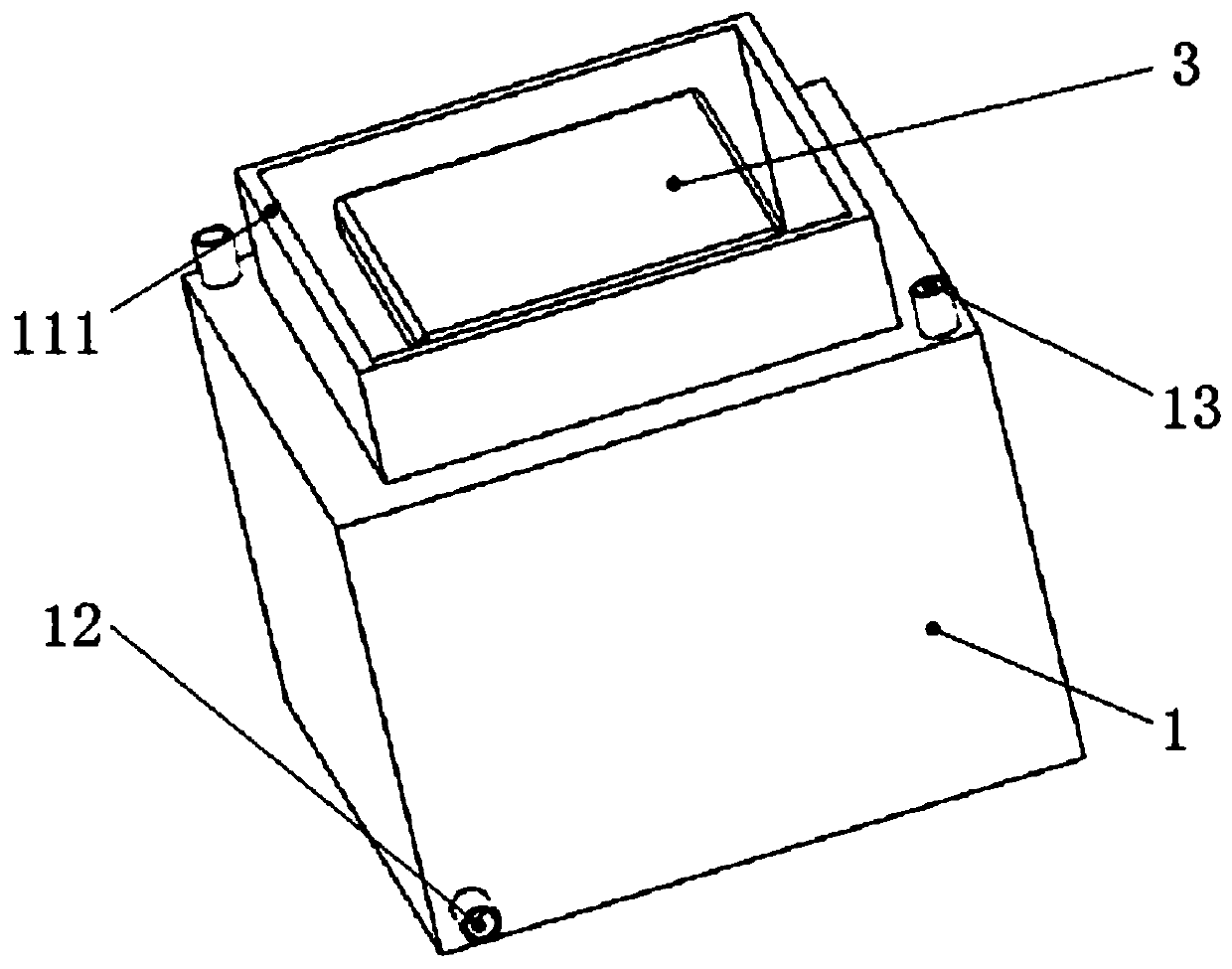
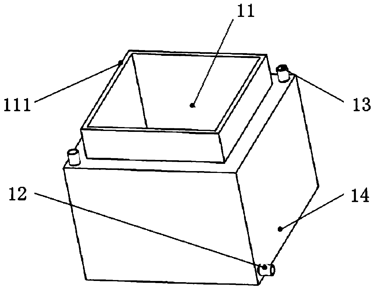
[0047] Such as Figure 1-Figure 5 As shown, an operating platform device for laser cladding includes a lifting platform and a cooling box 1;

[0048] The inner bottom of the cooling box 1 is provided with a partition tube 11 extending to the top of the cooling box 1, the top of the partition tube 11 is open, and the inner wall of the cooling box 1 is connected to the partition A coolant cavity is provided between the outer walls of the tubes 11, and the side wall of the cooling box 1 is provided with a coolant inlet I12 and a coolant inlet II communicating with the coolant cavity, and the top of the cooling box 1 is provided with There are two coolant outlets 13 communicating with the coolant cavity;

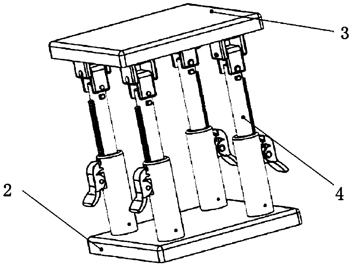
[0049] The lifting platform includes a lower plane 2 attached to the inner bottom of the cooling box 1, a cladding platform 3 and four lifting devices 4 located between the lower plane 2 and the cladding platform 3 ;

[0050]The lifting device 4 includes a support rod I41 con...


PUM


Abstract

The invention discloses an operating platform device for laser cladding, which includes a lifting platform and a cooling box; the inner bottom of the cooling box is provided with a partition tube extending to the top of the cooling box, and the side wall of the cooling box is provided with Coolant inlet I and coolant inlet II, the top of the cooling box is provided with two coolant outlets; the lifting platform includes a lower plane that fits the inner bottom of the cooling box, a cladding platform and a cladding platform located on the lower plane and cladding There are four lifting devices between the platforms; the lifting device includes a support rod I connected to the upper surface of the lower platform, a universal shaft connected to the lower surface of the cladding platform and a support rod II connected to the universal shaft. The invention can realize the lifting, tilting and tilting rotation of the cladding platform, ensure the ambient temperature during the cladding process, prevent the "collapse" phenomenon of the cladding layer, and can block the "splashed" powder during the cladding process and collect it. The role of powder.

Description

technical field [0001] The invention relates to an operating platform device for laser cladding with adjustable height angle, controllable temperature and recyclable waste materials. Background technique [0002] Laser cladding technology is a new surface modification technology that emerged with the development of high-power lasers in the 1970s. This technology rapidly heats and melts alloy powder or ceramic powder and the surface of the substrate under the action of laser beams. A rapid prototyping method for surface coatings that are metallurgically bonded to the base material. Using laser cladding technology, functional parts with arbitrary complex shapes, good mechanical properties and high dimensional accuracy can be obtained, which are suitable for small batches and customized complex functional parts. [0003] Laser cladding forming technology is widely used in the processing and manufacturing of important parts of automobiles and aerospace, maintenance, complex spe...

Claims


Application Information

Patent Timeline
Patent Type & Authority Patents(China)
IPC IPC(8): C23C24/10
CPCC23C24/10
Inventor 毕晓夕孙佳钰赵雨辛洪生于天彪王宛山
Owner NORTHEASTERN UNIV LIAONING
Learn More