Rowed pile box culvert structure and construction method thereof

A construction method and technology of pile boxes, which are applied to special box culvert structures and their construction fields, can solve problems such as uneven settlement at the bottom of box culverts, unsuitability for use, and too thick soft foundation, so as to avoid uneven settlement, Avoid waste and reduce the effect of construction links

Active Publication Date: 2017-05-31
XIAMEN MUNICIPAL ENGINEERING DESIGN INSTITUTE CO LTD
View PDF6 Cites 4 Cited by
  • Summary
  • Abstract
  • Description
  • Claims
  • Application Information

AI Technical Summary

Problems solved by technology

The foundation pit row pile support of the box culvert structure is a temporary structure with high cost, and the box culvert is abandoned after pouring
And this structure is not suitable for use on ultra-thick soft foundations. If the soft foundation is too thick, the problem of uneven settlement at the bottom of the box culvert will easily occur.

Method used


Image

  • Rowed pile box culvert structure and construction method thereof
  • Rowed pile box culvert structure and construction method thereof
  • Rowed pile box culvert structure and construction method thereof

Examples


Embodiment 1

[0048] This embodiment discloses a pile-row box culvert structure, which is a single-hole box culvert structure.

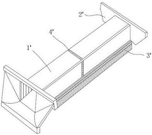
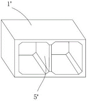
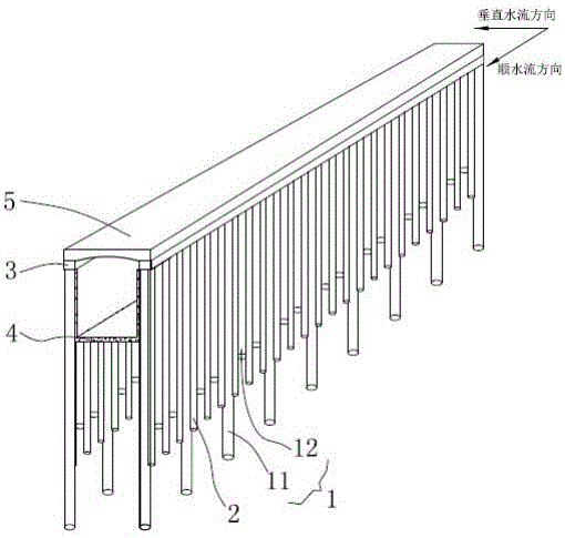
[0049] Such as Figure 3-5As shown, the single-hole box culvert structure of this embodiment includes side column row piles 1, high-pressure jet grouting piles 2, side crown beams 3, U-shaped bottom plate 4 and top plate 5. The side column row piles 1 are divided into two groups, which are arranged symmetrically on both sides, and high-pressure rotary jetting piles 2 are arranged between the two side column row piles 1 on each side to form a water-stop curtain. The side column pile 1 includes a long irrigation column pile 11 and a short irrigation column pile 12, and two short irrigation column piles 12 are arranged between the two long irrigation column piles 11, and the long irrigation column pile 11 is embedded in a moderately weathered rock formation or has a sufficient anchorage length Bearing layer plays the role of supporting the whole structure; the heigh...

Embodiment 2

[0061] This embodiment discloses a pile-row box culvert structure. The span of the box culvert is 9×8.8×9m, the clear height is 5.2m, the total length is about 81m, the thickness of the mud at the bottom of the box culvert is about 20m, and the elevation of the top plate of the box culvert is about 4.3m. The design elevation of the pavement is 8m, and the top elevation of the box culvert floor is -2.5m. According to needs, this embodiment is provided with three holes, which is a three-hole box culvert structure.

[0062] Such as Figure 9 As shown, the three-hole box culvert structure includes a row of side column piles 1, a central column 7, a high-pressure jet grouting pile 2, a side crown beam 3, a middle crown beam 6, a U-shaped bottom plate 4, and a top plate 5.

[0063] Such as Figure 11-12 As shown, the side column row piles 1 are divided into two groups, which are arranged symmetrically on both sides. High-pressure rotary spray piles 2 are arranged between the two s...


PUM


Abstract

The invention discloses a rowed pile box culvert structure and a construction method thereof. The rowed pile box culvert structure comprises side column rowed piles, high pressure jet grouting piles, side crown beams, U-shaped base plates and top plates, wherein the side column rowed piles are divided into two groups and are symmetrically distributed on two sides, high pressure jet grouting piles are arranged between two side column rowed piles on each side to form a water stopping curtain, the number of the side crown beams is two, the side crown beams are located above the two groups of side column rowed piles, the U-shaped base plates are cast between the groups of side column rowed piles, side walls of the U-shaped base plates are connected with the inner walls of the side column rowed piles, and the upper portions of the side column rowed piles are cast with the top plates integrally. The construction method of the structure comprises the steps that the row piles are supported, then the base plates and the top plates are cast by adopting inverse excavation construction, construction links are decreased, an original temporary structure for rowed pile supporting is changed into a perpetual structure, engineering structure waste is avoided, a constriction period is effectively shortened, and construction cost is reduced.

Description

technical field [0001] The invention relates to the technical field of traffic and water conservancy engineering, in particular to a special box culvert structure and a construction method thereof. Background technique [0002] Box culvert is a kind of culvert, which is generally used for drainage, passing people and vehicles. Box culverts are divided into single-hole box culverts and multi-hole box culverts according to needs. Such as figure 1 As shown, the existing single-hole box culvert is a closed frame structure, and its main components include reinforced concrete culvert body 1', wing wall 2', concrete foundation 3', deformation joint 4' and so on. Such as figure 2 As shown, the existing porous box culvert and figure 1 The single-hole box culvert structure is similar to that in which multiple culverts are arranged on the concrete culvert body 1', and vertical walls 5' are arranged between the culverts. The construction of box culverts generally adopts cast-in-pl...

Claims


Application Information

Patent Timeline
IPC IPC(8): E01F5/00
CPCE01F5/005
Inventor 黄瑛黄福祥郭志柳
Owner XIAMEN MUNICIPAL ENGINEERING DESIGN INSTITUTE CO LTD
Why Eureka
Try Eureka