Wharf desilting structure

A wharf and silt tank technology, applied in the field of wharf dredging structure, can solve problems such as poor operation, uneven mixing, and poor mixing effect, and achieve the effects of easy extraction, more uniform mixing, and good spraying effect

Inactive Publication Date: 2017-05-31
ZHEJIANG OCEAN UNIV
View PDF7 Cites 5 Cited by
  • Summary
  • Abstract
  • Description
  • Claims
  • Application Information

AI Technical Summary

Problems solved by technology

Therefore, it must be cleaned up. The current dredging method is to use dredgers to clean up the wharf, which costs too much and is very inconvenient to operate.
At the same time, for the comparison document with the application number "201520207741.7" and the invention title "a wharf dredging structure", the mixing effect is not good and the mixing is not uniform due to the mixing of mud and water through the air blowing pipes on both sides, and there will still be residues. At the same time, the water is absorbed through the drain pipe, which can not make good use of marine resources and cause a certain waste of materials. At the same time, the simple sealing cover cannot achieve a good sealing effect

Method used


Image

  • Wharf desilting structure
  • Wharf desilting structure
  • Wharf desilting structure

Examples


Embodiment 1

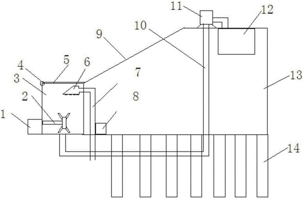
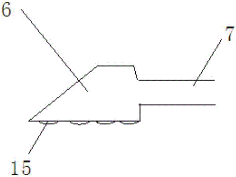
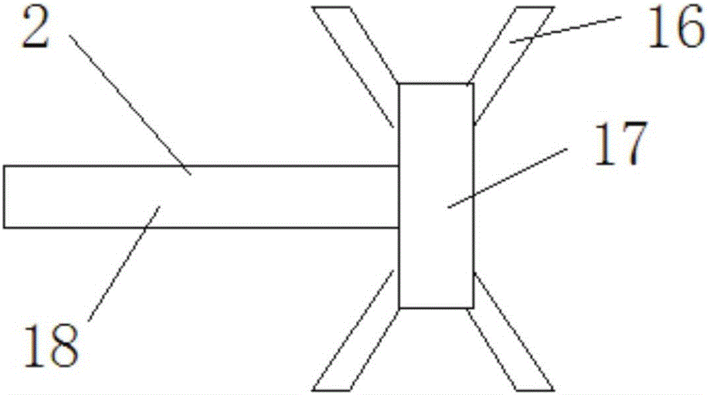
[0025] Embodiment one: if Figure 1-4 Shown, the present invention comprises dock body 13, and dock body 13 bottom is provided with fixed pile 14, and dock body 13 side is provided with mud box 3, and dock body 13 is provided with slope 9, and slope 9 one ends are connected with mud box 3, and mud The top of the box 3 is provided with an upper cover 5 through the connection device 4, an engine 1 is arranged on the outside of the mud box 3, and a stirring device 2 is arranged at one end of the engine 1, and the stirring device 2 is arranged inside the mud box 3, and the inside of the dock body 13 A mud storage device 12 is provided, and a mud pumping pipeline 10 is arranged between the mud storage device 12 and the mud pump 11 and between the mud pump 11 and the sludge tank 3, and one end of the mud pumping pipeline 10 is arranged at the bottom of the mud tank 3, and the sludge A sprinkler head 6 is arranged inside the tank 3, and the sprinkler head 6 is connected with the exte...

Embodiment 2

[0027] Embodiment two: the present invention comprises dock body 13, and the bottom of dock body 13 is provided with fixed pile 14, and one side of dock body 13 is provided with mud box 3, and dock body 13 is provided with slope 9, and one end of slope 9 is connected with mud box 3, The top of the mud tank 3 is provided with an upper cover 5 through the connection device 4, and the outside of the mud tank 3 is provided with an engine 1, and one end of the engine 1 is provided with a stirring device 2, and the stirring device 2 is arranged in the inside of the mud tank 3, and the dock body 13 A mud storage device 12 is arranged inside, and a mud pumping pipeline 10 is arranged between the mud storage device 12 and the mud pump 11 and between the mud pump 11 and the sludge tank 3, and one end of the mud pumping pipeline 10 is arranged at the bottom of the mud tank 3. A sprinkler head 6 is arranged inside the mud tank 3, and the sprinkler head 6 is connected with the external seab...

Embodiment 3

[0030] Embodiment three: the present invention comprises dock body 13, and the bottom of dock body 13 is provided with fixed pile 14, and one side of dock body 13 is provided with mud box 3, and dock body 13 is provided with slope 9, and one end of slope 9 is connected with mud box 3, The top of the mud tank 3 is provided with an upper cover 5 through the connection device 4, and the outside of the mud tank 3 is provided with an engine 1, and one end of the engine 1 is provided with a stirring device 2, and the stirring device 2 is arranged in the inside of the mud tank 3, and the dock body 13 A mud storage device 12 is arranged inside, and a mud pumping pipeline 10 is arranged between the mud storage device 12 and the mud pump 11 and between the mud pump 11 and the sludge tank 3, and one end of the mud pumping pipeline 10 is arranged at the bottom of the mud tank 3. A sprinkler head 6 is arranged inside the mud tank 3, and the sprinkler head 6 is connected with the external se...


PUM


Abstract

The invention discloses a wharf desilting structure. The wharf desilting structure comprises a wharf body; a fixed pile is arranged at the bottom of the wharf body; a silt box is arranged on one side of the wharf body; the wharf body is provided with a slope; one end of the slope is connected with the silt box; an upper cover is arranged at the top of the silt box through a connecting device; an engine is arranged on the outer side of the silt box; a stirring device is arranged at one end of the engine, and is arranged in the silt box; a silt storage device is arranged in the wharf body; silt extracting pipes are respectively arranged between the silt storage device and a silt pump and between the silt pump and the silt box; one ends of the silt extracting pipes are arranged at the bottom of the silt box; a spraying head is arranged in the silt box, and is connected with external seabed water currents through a water extracting channel; and a water pump is arranged on the water extracting channel. The wharf desilting structure has the characteristics of better desilting effect and better environmental protecting effect.

Description

technical field [0001] The invention belongs to the technical field of ship building, in particular to a wharf dredging structure. Background technique [0002] The wharf is a building specially designed for passengers to get on and off, and cargo to be loaded and unloaded by the sea and rivers. Usually found in commercial cities with well-developed water and land transportation. Human beings use the wharf as a ferry berth to board and disembark passengers and goods, and secondly, it may also be a landmark to attract tourists and date gatherings. Common buildings or facilities around the terminal include cruise ships, ferries, container ships, warehouses, customs, pontoons, seagulls, fish markets, seaside promenades, stations, restaurants, or shopping malls. [0003] Gravity dock. It is stable by the weight of the building itself and the weight of the filler in the structural range. It has good structural integrity, is durable, and is easy to repair after damage. There ar...

Claims


Application Information

Patent Timeline
Patent Type & Authority Applications(China)
IPC IPC(8): E02B3/02E02F5/28
CPCE02B3/023E02F5/28
Inventor 沈良朵
Owner ZHEJIANG OCEAN UNIV
Why Eureka
Try Eureka