Prefabricated foundation structure and its construction method

A basic structure, prefabricated assembly technology, applied in basic structure engineering, construction, etc., can solve problems such as high construction cost, environmental pollution, and difficult to control concrete quality.

Active Publication Date: 2019-09-27
GUANGZHOU ELECTRIC POWER DESIGN INST
View PDF7 Cites 0 Cited by
  • Summary
  • Abstract
  • Description
  • Claims
  • Application Information

AI Technical Summary

Problems solved by technology

The cast-in-place reinforced concrete foundation has the following disadvantages: it must be constructed on site, and wet work has a great impact on the environment of the construction site, which does not meet the requirements of green environmental protection; the foundation can only be used once, and the resource utilization rate is low, resulting in waste of resources
Moreover, the cast-in-place foundation is made on-site by the construction unit, and the quality of the concrete is difficult to control; the foundation needs to be molded, reinforced, and concrete poured at the construction site, and the superstructure can only be installed after the concrete has reached the design strength after curing, and the construction period is long
In order to eliminate the above defects of cast-in-place concrete foundation, with the continuous development of construction technology, prefabricated reinforced concrete foundation appears, which can solve the problems of high construction cost, environmental pollution, and poor reliability of construction quality, but the existing prefabricated The structure of the concrete foundation is relatively complicated, which leads to difficult construction technology and difficult assembly; especially in some situations where the uplift force or downforce is large, or the construction soil layer is weak, the reliability of the foundation will be reduced due to the low structural strength , poor service life

Method used


Image

  • Prefabricated foundation structure and its construction method
  • Prefabricated foundation structure and its construction method
  • Prefabricated foundation structure and its construction method

Examples


Embodiment Construction

[0038] In order to make the object, technical solution and advantages of the present invention clearer, the present invention will be further described in detail below in conjunction with the accompanying drawings and specific implementation methods. It should be understood that the specific embodiments described here are only used to explain the present invention, and do not limit the protection scope of the present invention.

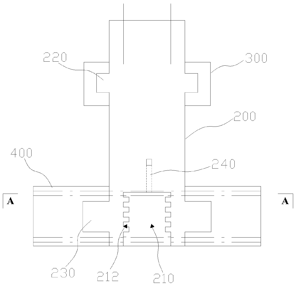
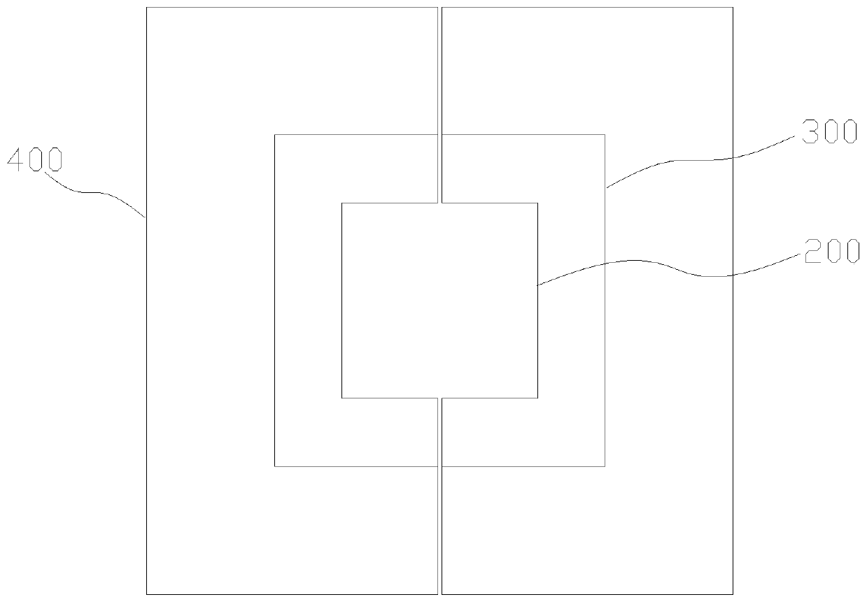
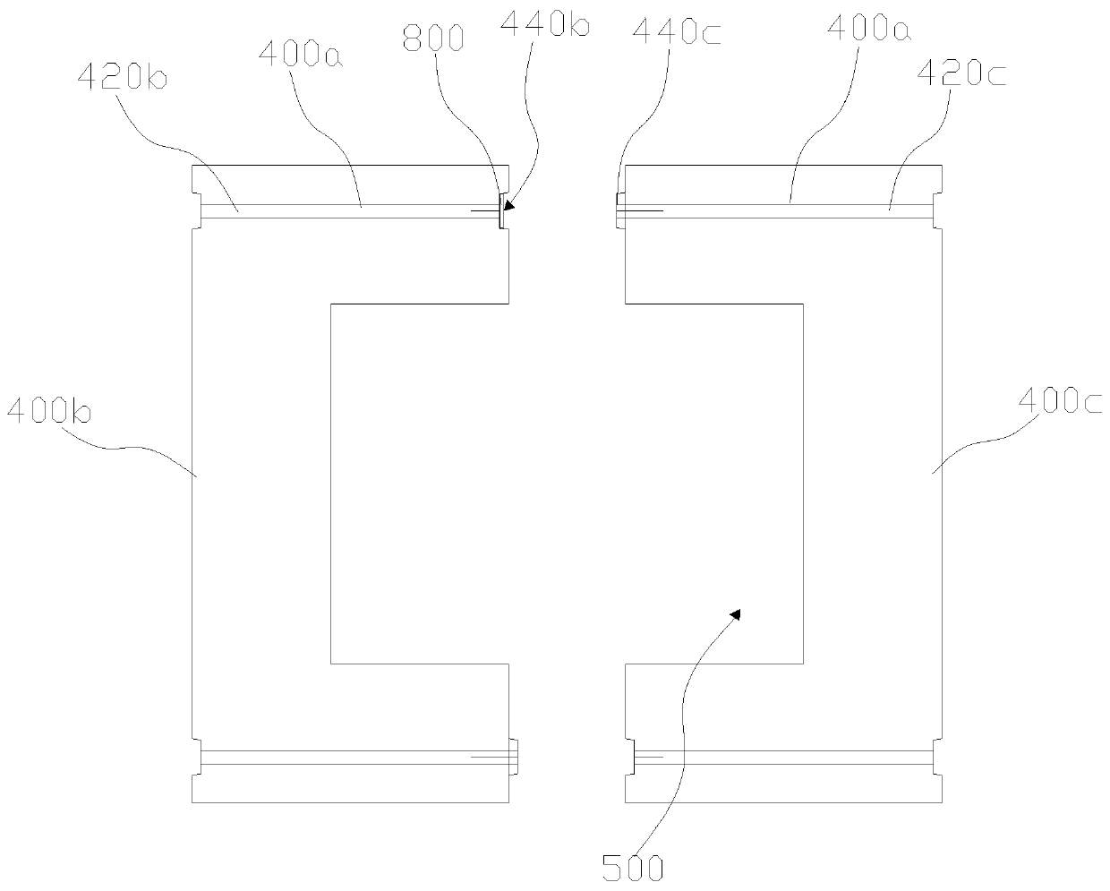
[0039] Such as Figure 1 to Figure 5 As shown, a prefabricated foundation structure includes a pile foundation 100, the pile foundation 100 is arranged in the foundation pit; a central column 200, the bottom of the central column 200 is recessed inwardly to form an accommodating groove 210, and the pile The base 100 is embedded in the accommodating groove 210, and the central column 200 includes a first assembly part 220 and a second assembly part 230; a top fastener 300, and the top fastener 300 is sleeved on the first assembly part 220 ; and the bo...


PUM


Abstract

The invention discloses a prefabricated assembly type foundation structure and a construction method of the prefabricated assembly type foundation structure. The structure comprises a pile foundation, a center column, a top fixing part and a bottom fixing part. The pile foundation is arranged in a foundation pit. The bottom of the center column is concaved inwards to form a containing groove. The pile foundation is embedded in the containing groove. The center column comprises a first assembly portion and a second assembly portion. The top fixing part is arranged on the first assembly portion in a sleeving mode. The bottom fixing part is arranged on the foundation pit in a pressed mode. The bottom fixing part is arranged on the second assembly portion in a sleeving mode. Accordingly, the foundation construction technological steps can be greatly simplified, the construction difficulty is effectively lowered, the structural strength of the foundation is ensured under large upward pulling force or downward pressure or under soft soil layer construction conditions, then, high using reliability is ensured, and meanwhile the environmental pollution problem caused by on-site construction can be avoided.

Description

technical field [0001] The invention relates to the technical field of substation facility construction, in particular to a prefabricated basic structure and a construction method thereof. Background technique [0002] At present, the foundation of the domestic substation support structure mainly adopts the form of cast-in-place reinforced concrete foundation. Commonly used cast-in-place reinforced concrete foundations include independent foundation, shell foundation and pile foundation. The cast-in-place reinforced concrete foundation has the following disadvantages: it must be constructed on site, and wet work has a great impact on the environment of the construction site, which does not meet the requirements of green environmental protection; the foundation can only be used once, and the resource utilization rate is low, resulting in waste of resources. Moreover, the cast-in-situ foundation is made on-site by the construction unit, and the quality of the concrete is diffi...

Claims


Application Information

Patent Timeline
Patent Type & Authority Patents(China)
IPC IPC(8): E02D27/42E02D27/44
Inventor 万新方翠苏春发颜天佑
Owner GUANGZHOU ELECTRIC POWER DESIGN INST
Why Eureka
Try Eureka