

Wall cement laying equipment used in construction site
A construction site and wall technology, applied in construction, building construction, construction material processing, etc., can solve the problems of dangerous workers' clothes pollution, time-consuming and labor-intensive laying process, and cement falling off, etc.
- Summary
- Abstract
- Description
- Claims
- Application Information
AI Technical Summary
Problems solved by technology
Method used
Image

Examples
Embodiment 1
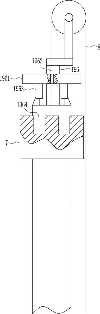
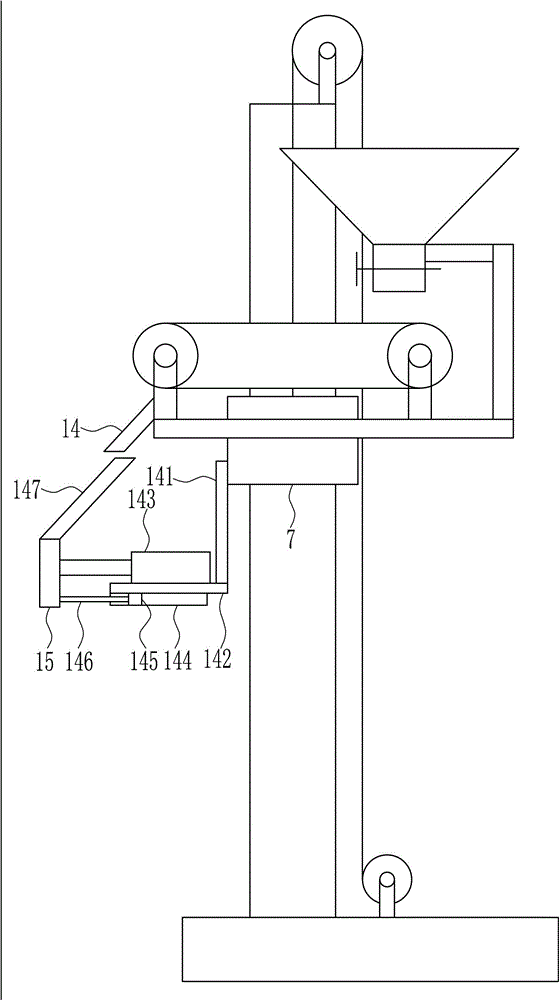
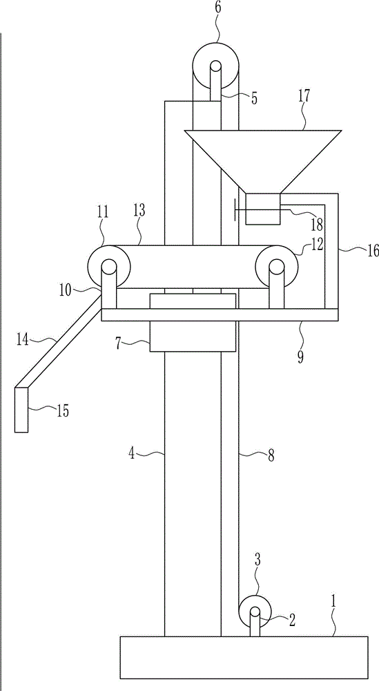
[0037] A construction site with wall cement laying equipment, such as Figure 1-6 As shown, it includes base plate 1, first leg 2, electric reel 3, guide rail 4, second leg 5, fixed pulley 6, guide sleeve 7, pull wire 8, placement plate 9, third leg 10, driving wheel 11 , driven wheel 12, conveyor belt 13, first slant plate 14, laying plate 15, first L-shaped bar 16, hopper 17 and electric control valve 18, the upper side of bottom plate 1 is installed with the first leg 2 by welding, the first An electric reel 3 is rotatably connected to the foot 2, and a guide rail 4 is installed on the upper side of the bottom plate 1 by welding. The guide rail 4 is located on the left side of the first foot 2. The upper end of the guide rail 4 is installed with a second foot by welding 5. The fixed pulley 6 is rotatably connected to the second leg 5, and the guide sleeve 7 is slidably connected to the guide rail 4. The upper end of the guide sleeve 7 is connected with a pull wire 8, and th...
Embodiment 2
[0039] A construction site with wall cement laying equipment, such as Figure 1-6 As shown, it includes base plate 1, first leg 2, electric reel 3, guide rail 4, second leg 5, fixed pulley 6, guide sleeve 7, pull wire 8, placement plate 9, third leg 10, driving wheel 11 , driven wheel 12, conveyor belt 13, first slant plate 14, laying plate 15, first L-shaped bar 16, hopper 17 and electric control valve 18, the upper side of bottom plate 1 is installed with the first leg 2 by welding, the first An electric reel 3 is rotatably connected to the foot 2, and a guide rail 4 is installed on the upper side of the bottom plate 1 by welding. The guide rail 4 is located on the left side of the first foot 2. The upper end of the guide rail 4 is installed with a second foot by welding 5. The fixed pulley 6 is rotatably connected to the second leg 5, and the guide sleeve 7 is slidably connected to the guide rail 4. The upper end of the guide sleeve 7 is connected with a pull wire 8, and th...
Embodiment 3
[0042] A construction site with wall cement laying equipment, such as Figure 1-6 As shown, it includes base plate 1, first leg 2, electric reel 3, guide rail 4, second leg 5, fixed pulley 6, guide sleeve 7, pull wire 8, placement plate 9, third leg 10, driving wheel 11 , driven wheel 12, conveyor belt 13, first slant plate 14, laying plate 15, first L-shaped bar 16, hopper 17 and electric control valve 18, the upper side of bottom plate 1 is installed with the first leg 2 by welding, the first An electric reel 3 is rotatably connected to the foot 2, and a guide rail 4 is installed on the upper side of the bottom plate 1 by welding. The guide rail 4 is located on the left side of the first foot 2. The upper end of the guide rail 4 is installed with a second foot by welding 5. The fixed pulley 6 is rotatably connected to the second leg 5, and the guide sleeve 7 is slidably connected to the guide rail 4. The upper end of the guide sleeve 7 is connected with a pull wire 8, and th...
PUM
 Abstract
Description
Claims
Application Information