Stirling motor and defrosting unit

A technology of heating tubes and heat exchange components, which is applied to engine components, mechanical equipment, machines/engines, etc., can solve problems such as easy frosting and affect the working efficiency of Stirling motors, and achieve the effect of ensuring working efficiency

Active Publication Date: 2017-05-31
CHINA STIRLING ENGINE MFG
View PDF7 Cites 1 Cited by
  • Summary
  • Abstract
  • Description
  • Claims
  • Application Information

AI Technical Summary

Problems solved by technology

[0003] The cold end of the Stirling motor is prone to frosting due to the cooling effect. At present, a defrosting unit is fixed on the cold end of the Stirling motor to perform defrosting work, and the heating in the current defrosting unit One part of the component is directly in contact with the cold end, and the other part is exposed, and in this way, the heating component heats the cold end while heating the air, which affects the working efficiency of the Stirling motor

Method used


Image

  • Stirling motor and defrosting unit
  • Stirling motor and defrosting unit
  • Stirling motor and defrosting unit

Examples


Embodiment 1

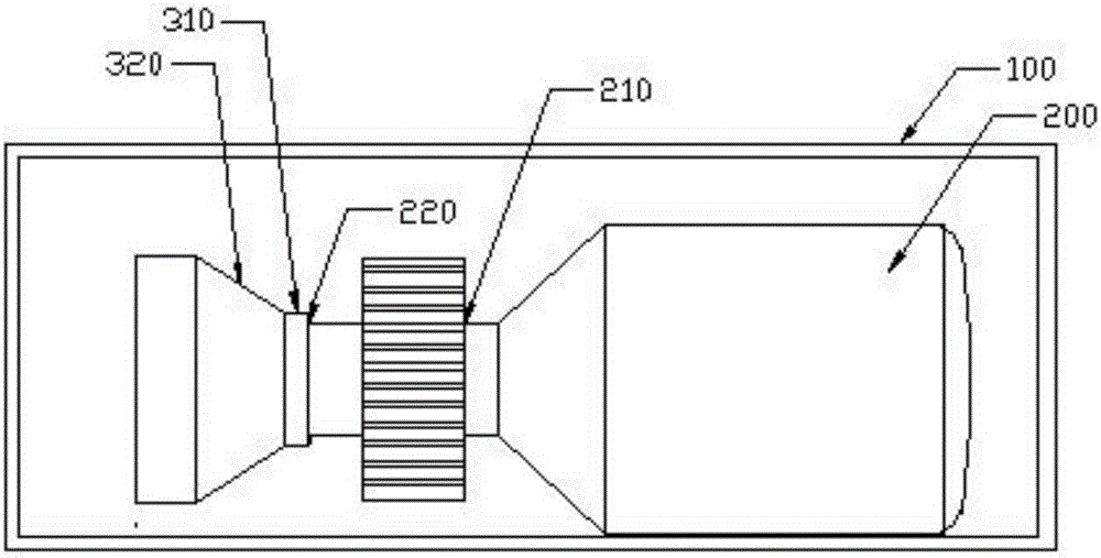
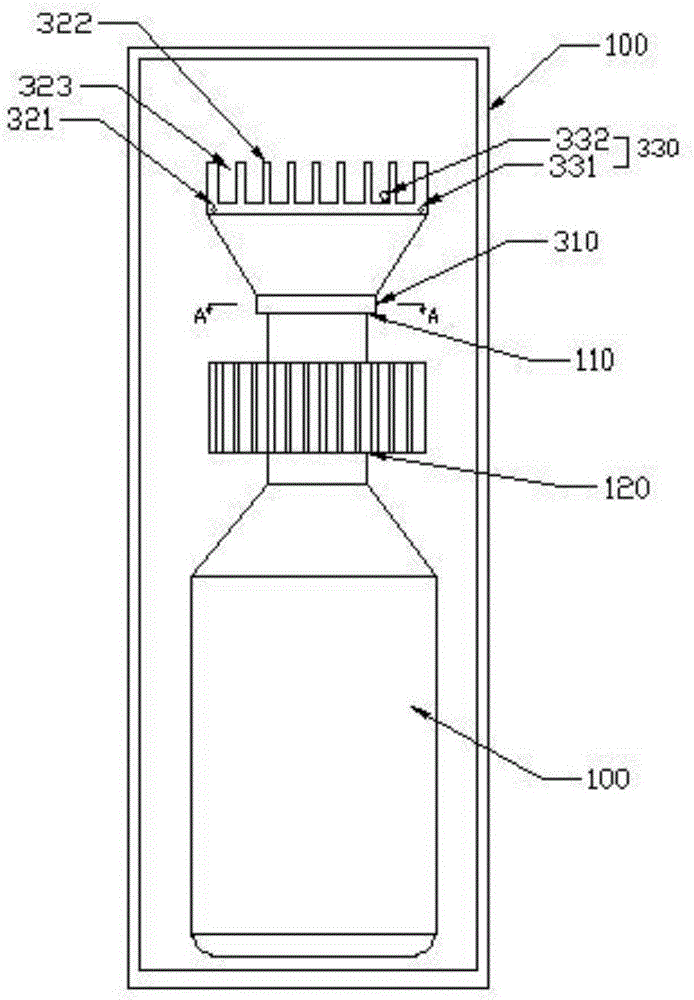
[0026] Embodiment 1, with reference to Figure 1-2 , a Stirling motor with a defrosting unit, including a housing 100 and a motor body 200, the motor body 200 includes a cold end 220 and a hot end 210, the cold end 220 is provided with a defrosting unit, and the defrosting unit includes a heat exchange Component 320, heating component 330 and fixed structure 310, the heat exchange component 320 is fixed to the cold end 220 through the fixed structure 310; the heating component 330 heats the heat exchange component 320 when working; the heating component 330 includes a heating tube 331, and the heat exchange component 320 On one side close to the fixing structure 310 , the shape of the embedding groove 321 is adapted to the heating pipe 331 , and the heating pipe 331 is embedded in the embedding groove 321 and arranged. There are two heating tubes 331, and the number of embedded grooves 321 corresponds to the number of heat exchange tubes. The arrangement direction of the heat...

Embodiment 2

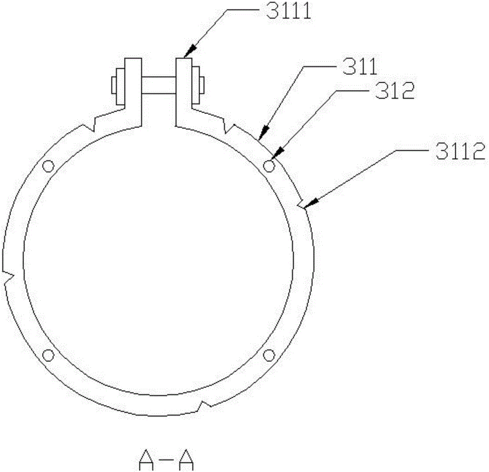
[0031] Embodiment 2, with reference to Figure 4As shown, the difference from Example 1 is that the heat exchange fins 322 and strip-shaped heat exchange protrusions in Example 2 are respectively arranged on both sides of the heat exchange plate 325, and the heat exchange fins 322 The length direction of the strip-shaped heat exchange protrusion is parallel to the length direction of the strip-shaped heat exchange protrusion; the embedded groove 321 is set on the strip-shaped heat exchange protrusion, and the number of the heating tubes 331 is set to two. 321 and the number of strip-shaped heat exchange protrusions. The number of the heating tubes 331 is correspondingly set to two, and there is a space between the two strip-shaped heating protrusions. The fixing structure 310 includes a round tube hoop 311, the round tube hoop 311 is fixed to the heat exchange plate 325, the round tube hoop 311 includes a fastening unit 3111, and the round tube hoop 311 fastens the cold end 22...

Embodiment 3

[0032] In Embodiment 3, the defrosting unit in Embodiment 1 is used alone, and the defrosting unit can be fixed on any Stirling motor through the fixing structure 330 to realize the defrosting work.


PUM


Abstract

The invention relates to a defrosting unit of a Stirling motor and the Stirling motor. The defrosting unit is used for being fixed to the cold end of the Stirling motor and comprises a heat exchange assembly, a heating assembly and a fixing structure, and the heat exchange assembly is fixed to the cold end through the fixing structure. The heating assembly heats the heat exchange assembly during work and comprises a heating pipe. An embedding groove is formed in the side, close to the fixing structure, of the heat exchange assembly, the shape of the embedding groove is matched with that of the heating pipe, and the heating pipe is embedded into the embedding groove. The defrosting unit is in contact with the heating assembly through the heat exchange assembly, the heating assembly cannot be directly exposed to air, the heating assembly is heated, and the heat exchange assembly is in contact with the cold end directly. Due to the fact that the heat exchange efficiency of a gas medium is larger than that of a solid medium, the heating pipe is embedded into the heat exchange assembly, heat is preferentially conducted to the cold end and cannot spread to the air easily under the action of the heat balance theory, and the work efficiency of the Stirling motor is guaranteed.

Description

technical field [0001] The invention relates to the technical field of motors, in particular to a defrosting unit of a Stirling motor. Background technique [0002] The Stirling engine is another type of reciprocating power machinery besides the steam engine and the internal combustion engine; the Stirling engine can be used not only as a prime mover, but also as a refrigerator, heat pump or pressure generator. Its structure includes an excitation structure, a mechanical power device, and a heat exchange chamber. The mechanical power device compresses or expands the working fluid inside the heat exchange chamber through mechanical movement, and these working fluids are generally inert gases. When the inert gas is compressed, the temperature decreases, and the corresponding The expansion action of the motor will cause the temperature to rise, and through such a cycle, the cold end and the hot end can be formed on the outside of the motor, respectively, to play the function of...

Claims


Application Information

Patent Timeline
Patent Type & Authority Applications(China)
IPC IPC(8): F02G1/053F02G1/055
CPCF02G1/053F02G1/055F02G2255/10
Inventor 程路
Owner CHINA STIRLING ENGINE MFG
Why Eureka
Try Eureka