Supercharge Your Innovation With Domain-Expert AI Agents!

Micro-dynamic-fuel-return bypass type electronic control fuel injector with hydraulic feedback function

An electronically controlled fuel injection and force feedback technology, applied in the direction of engine components, fuel injection devices, machines/engines, etc., can solve the problems of difficulty in achieving fast seat response of the needle valve, inconsistent injection process, and large dynamic oil return volume. Achieve the effect of realizing micro-dynamic oil return function, reducing abnormal fuel injection conditions and improving emissions

Active Publication Date: 2017-05-31
HARBIN ENG UNIV
View PDF10 Cites 0 Cited by
  • Summary
  • Abstract
  • Description
  • Claims
  • Application Information

AI Technical Summary

Problems solved by technology

However, it is difficult for conventional electronically controlled injectors to achieve this
Secondly, at present, most domestic electronically controlled fuel injectors use a two-position two-way high-speed solenoid valve to control the fuel injection process. The two-position two-way valve is always open during the fuel injection process. Large oil volume, resulting in energy loss
At the same time, the limitation of the diameter of the inlet and outlet throttle holes and the existence of dynamic oil return also make it difficult to achieve a fast seat response of the needle valve.
In addition, when a large amount of fuel is injected, the fluctuation of the fuel pressure of the high-pressure common rail will cause the inconsistency of the injection process of each cylinder

Method used


Image

  • Micro-dynamic-fuel-return bypass type electronic control fuel injector with hydraulic feedback function
  • Micro-dynamic-fuel-return bypass type electronic control fuel injector with hydraulic feedback function
  • Micro-dynamic-fuel-return bypass type electronic control fuel injector with hydraulic feedback function

Examples


Embodiment Construction

[0021] The present invention is described in more detail below in conjunction with accompanying drawing example:

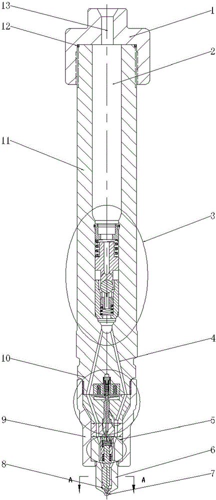
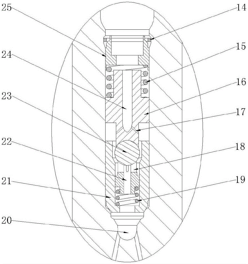
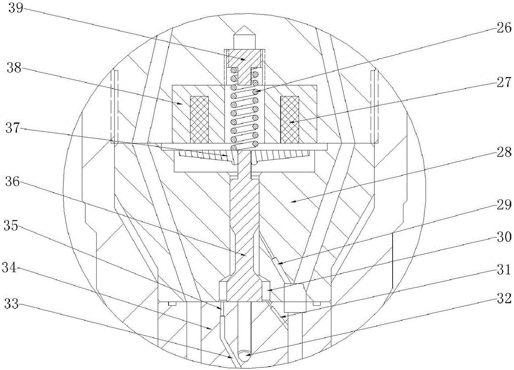
[0022] combine Figure 1-5 , the main structure of a micro-dynamic oil return bypass electronically controlled fuel injector with hydraulic feedback in the present invention includes a fuel injector head 1, a fuel injector body 11, a flow limiting valve assembly 3, a solenoid valve assembly 10, a tight cap 9. Needle valve assembly 5, nozzle 6. The fuel injector head 1 is connected with the fuel injector body 11 through threads, and is sealed with a sealing ring 12 placed on the fuel injector body 11 . The main oil inlet hole 13 on the injector head 1 communicates with the accumulator chamber 2 in the injector body 11 . Below the injector body 11 is a solenoid valve assembly 10 , a nozzle 6 and a needle valve assembly 5 , which are assembled and connected by a tight cap 9 . The flow limiting valve assembly 3 is placed inside the fuel injector body 11, and its st...


PUM


Abstract

The invention aims to provide a micro-dynamic-fuel-return bypass type electronic control fuel injector with the hydraulic feedback function. The micro-dynamic-fuel-return bypass type electronic control fuel injector with the hydraulic feedback function comprises a fuel injector head, a fuel injector body, a flow limiting valve assembly, an electromagnetic valve assembly, a needle valve limiting sleeve, a spray nozzle and a needle valve body. A pressure accumulation cavity is formed in the fuel injector body and communicates with a main fuel inlet hole and the flow limiting valve assembly, and it is guaranteed that under the condition of a large fuel injection amount, the fuel injection process of each cylinder is stable. The flow limiting valve assembly is arranged below the pressure accumulation cavity and prevents abnormal fuel injection from continuously proceeding. The bottom of the fuel injector body is provided with the electromagnetic valve assembly, and a balance valve rod is driven by electromagnetic force to move. A two-position three-way type electromagnetic valve enables the dynamic fuel return amount to be greatly reduced in the fuel injection process. A control sliding block is arranged in a control cavity and makes contact with a middle block, and the control sliding block has the functions of reducing the fuel injection rate in an injection initial period and accelerating response of seating of a needle valve. A hydraulic feedback fuel path processed in the middle block further enhances the effects of reducing the fuel injection rate in the injection initial period and accelerating response of seating of the needle valve. No static pressure difference exists in the fuel injector, the fuel injector avoids static leakage, and the hydraulic efficiency of a system is improved.

Description

technical field [0001] The invention relates to an engine fuel injection device. Background technique [0002] In order to optimize the fuel economy and emission indicators of diesel engines, the electronically controlled fuel injectors of diesel engines on the market currently adopt high-speed electromagnetic switch valve control, which has the advantages of fast system response, high control precision, flexible control strategy and reliable working performance. Etc. However, with the gradual increase of fuel injection pressure, the performance shortcomings of conventional electronically controlled injectors are also revealed. [0003] First of all, on the one hand, the fuel injector needs to reduce the emission of nitrogen oxides, which requires controlling the instantaneous fuel injection rate during the fuel injection process and reducing the fuel injection rate at the initial stage of injection. On the other hand, at the end of the injection process, the injector must...

Claims


Application Information

Patent Timeline
IPC IPC(8): F02M47/02F02M51/06F02M61/10F02M61/18F02M63/00
CPCF02M47/027F02M51/061F02M61/10F02M61/1893F02M63/0017F02M63/0035F02M63/0036F02M63/007
Inventor 范立云马修真
Owner HARBIN ENG UNIV
Features
  • R&D
  • Intellectual Property
  • Life Sciences
  • Materials
  • Tech Scout
  • Unparalleled Data Quality
  • Higher Quality Content
  • 60% Fewer Hallucinations
Learn More