Fan transmission device for automobile engine cooling

An automobile engine and fan transmission technology, applied in the direction of engine cooling, engine components, machines/engines, etc., can solve the problems of engine compartment pollution, inability to effectively lubricate grease, and inability to ensure the transmission performance of bearings, so as to ensure cleanliness and avoid dumping. oil effect

Pending Publication Date: 2017-05-31
ZHEJIANG NESSRAL MACHINERY
View PDF8 Cites 2 Cited by
  • Summary
  • Abstract
  • Description
  • Claims
  • Application Information

AI Technical Summary

Problems solved by technology

[0004] During the use of the above-mentioned transmission fan wheels for automobile cooling, lubricating oil needs to be added regularly to maintain the bearings, and the new grease injected during maintenance enters the two bearing working cavities through the straight-through pressure oiling cup, and the grease is easy to adhere to On the inner wall of the working cavity and the outer peripheral surface of the transmission shaft, the grease cannot effectively reach the bearing grooves at both ends for lubrication; at the same time, when the bearing rotates at high speed, due to the centrifugal force and the rolling of the bearing balls, the grease cannot Effectively lubricate the bearing groove surface and the balls, resulting in the grease in the working cavity of the two bearings unable to enter

Method used


Image

  • Fan transmission device for automobile engine cooling
  • Fan transmission device for automobile engine cooling
  • Fan transmission device for automobile engine cooling

Examples


Example Embodiment

[0026] The following are specific embodiments of the present invention in conjunction with the accompanying drawings to further describe the technical solutions of the present invention, but the present invention is not limited to these embodiments.

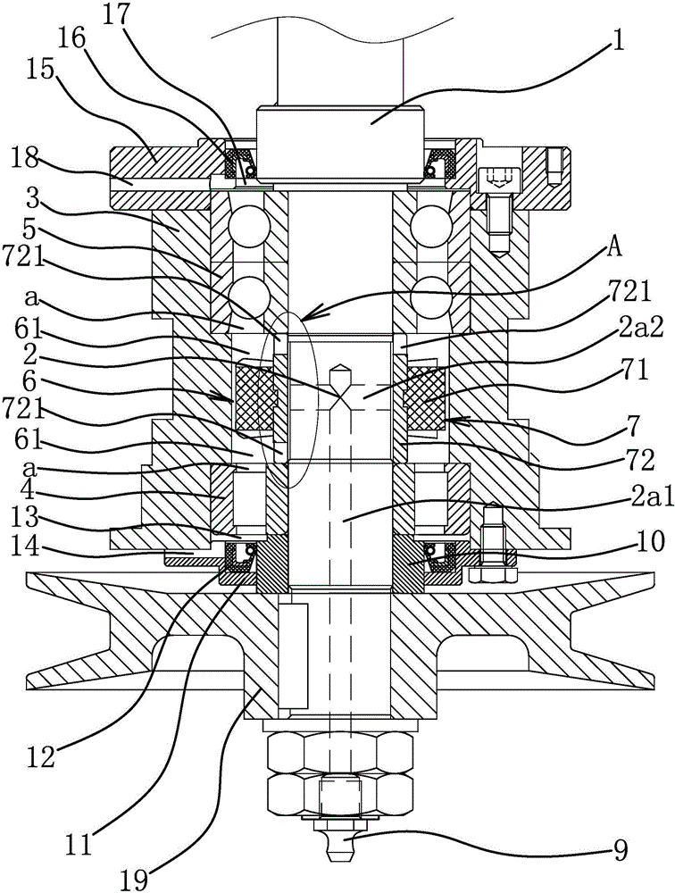
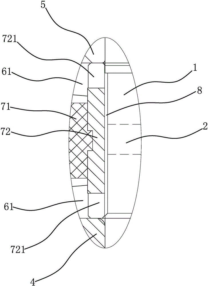
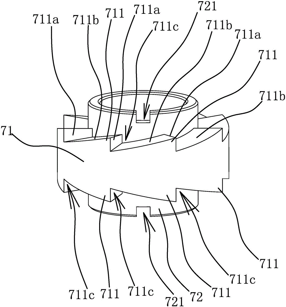
[0027] The fan transmission device for cooling the automobile engine includes a transmission shaft 1, an oil injection channel 2, a main oil channel 2a1, an oil distribution channel 2a2, a support sleeve 3, a bearing 4, a bearing 2 5, a channel a, a working cavity 6, and an oil storage cavity 61. Fan blade spacer 7, fan wheel 71, fan blade teeth 711, oil pushing surface 711a, oil guide slope 711b, V-shaped port 711c, clamping column 712, sleeve 72, oil outlet groove 721, clamping hole 722, oil clearance gap 8. Oil injection nozzle 9, shaft sleeve 10, oil seal seat 11, oil seal 12, seal cavity 13, oil discharge hole 14, connecting plate 15, oil seal 2, seal cavity 2, 17, oil discharge hole 18, fan drive Round 19.

[0028] Specifically...


PUM

PropertyMeasurementUnit
Central angleaaaaaaaaaa

Abstract

The invention provides a fan transmission device for automobile engine cooling, belongs to the technical field of machinery and achieves the effect that grease can rapidly and effectively reach a trench of a bearing for lubrication. The fan transmission device for automobile engine cooling comprises a transmission shaft and an oil injection channel, the transmission shaft is sleeved with a supporting sleeve, a first bearing and a second bearing are arranged between the inner walls of the two ends of the supporting sleeve and the transmission shaft, and a work cavity is formed between the inner end of the first bearing and the inner end of the second bearing; and the work cavity is internally provided with a fan blade spacer bush capable of rotating along with the transmission shaft, the fan blade spacer bush separates the work cavity into two oil storage cavities communicating with the oil injection channel, and the fan blade spacing bush is provided with a fan blade wheel capable of generating thrust towards the oil storage cavities on the two sides. Through design of the fan blade spacer bush of a special structure and an oil discharging hole, the grease in the work cavity can rapidly and effectively reach trenches of the bearings for lubrication, the phenomenon of oil shedding can also be avoided, and cleanliness of the device is guaranteed.

Description

technical field [0001] The invention belongs to the technical field of machinery, and relates to a fan transmission device for cooling an automobile engine. Background technique [0002] At present, in the known cooling system of the rear engine of the bus, the engine cooling water tank is arranged on the side of the engine, and a suction fan is used to cool the cooling water tank. As the fan that helps the cooling water tank to dissipate heat, its power is generally obtained by the fan drive wheel that is fixedly connected with it and can drive it to rotate, and the V belt that is connected between the fan drive wheel and the engine crank wheel. [0003] For example, the Chinese patent [Application No.: 201210047978.4; Application Publication No.: CN 103291649A] discloses a transmission fan wheel for automobile cooling, including a base, a fixed bracket installed on the base, a fan wheel and a fan wheel shaft, and a circular fan wheel is arranged on the fixed bracket. An a...

Claims


Application Information

Patent Timeline
IPC IPC(8): F04D29/063F04D29/056F01P5/04
CPCF01P5/04F04D29/056F04D29/063F01P2050/22
Inventor 徐时聪樊美刚高奂
Owner ZHEJIANG NESSRAL MACHINERY
Why Eureka
Try Eureka