Pedestal type radial thrust bearing device

A radial thrust and bearing device technology, applied in the direction of hydroelectric power generation, engine components, machines/engines, etc., can solve the problems of increasing the distance between the water turbine and the generator, inconvenient installation of the unit, and difficulty in installation and maintenance, so as to save manufacturing costs, The effect of reducing the external size and securing economic benefits

Inactive Publication Date: 2020-06-26
湖南云箭集团有限公司
View PDF6 Cites 0 Cited by
  • Summary
  • Abstract
  • Description
  • Claims
  • Application Information

AI Technical Summary

Problems solved by technology

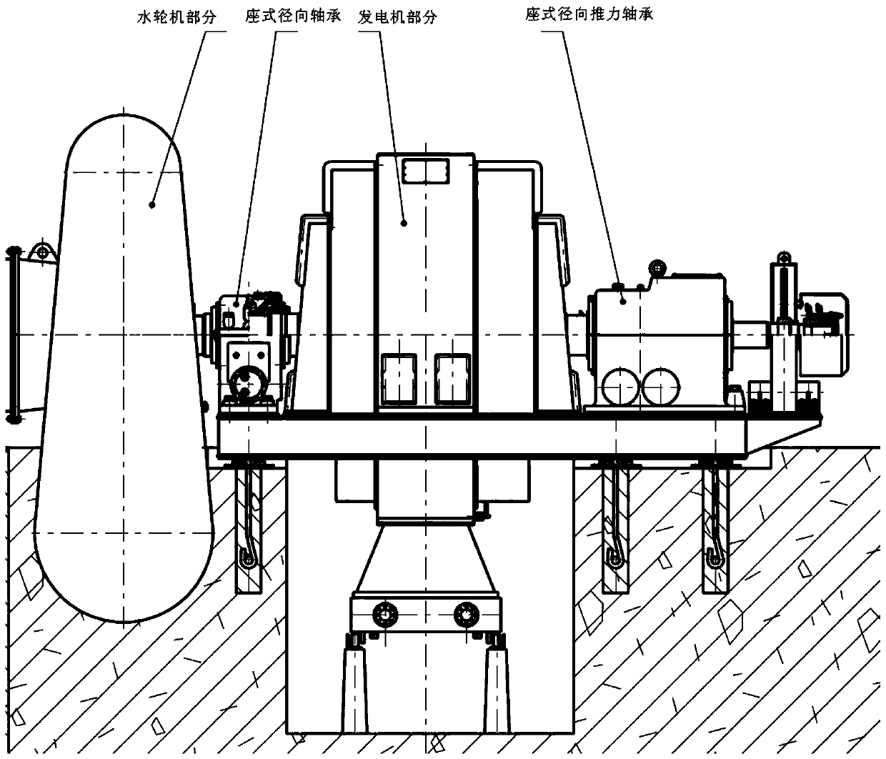
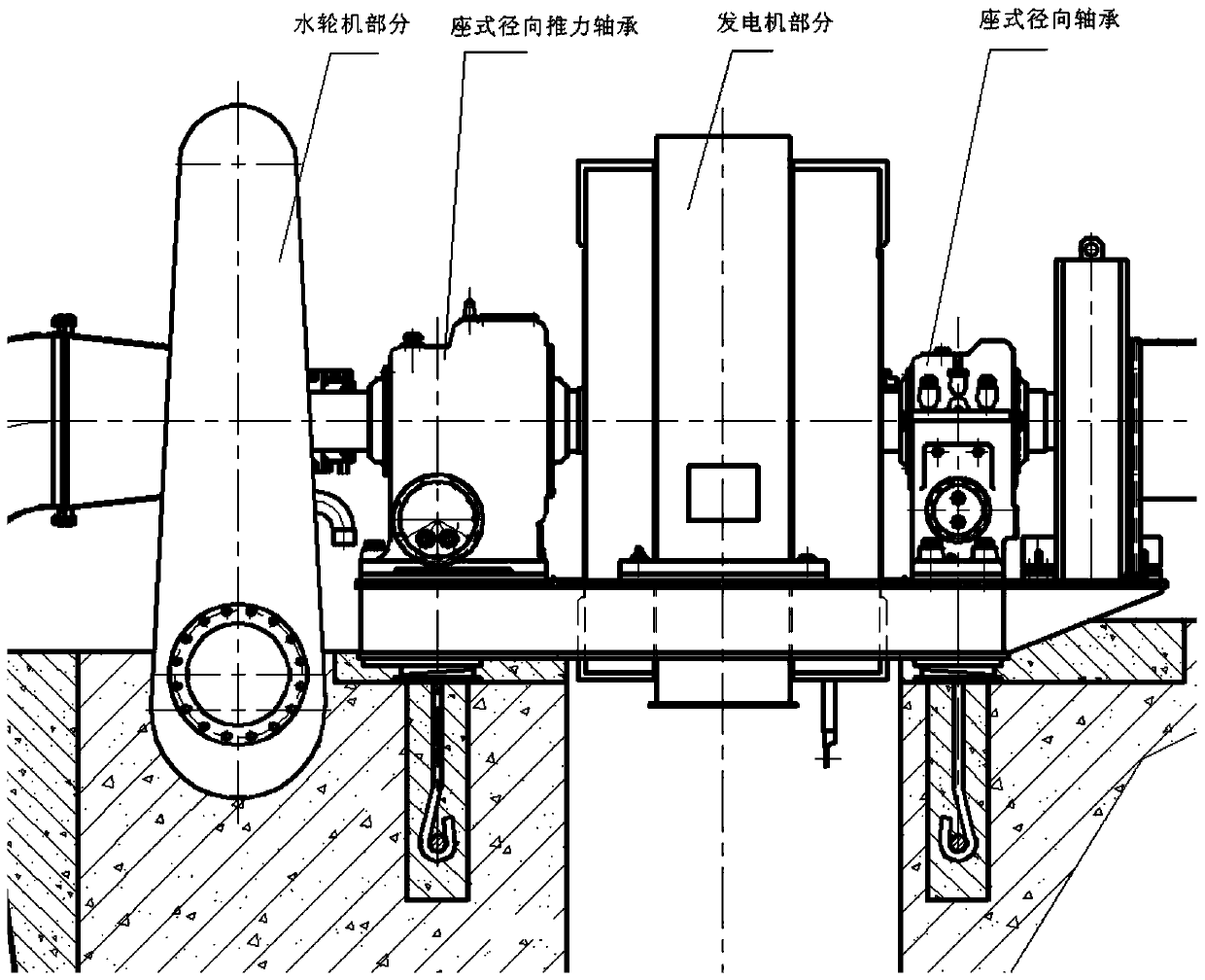
Due to the difficulty in installation and maintenance of large and medium-sized horizontal turbine units, we often set the seat type radial thrust bearing at the end of the unit near the generator to meet the needs of unit installation, but its structure often brings harm to actual processing. The shaft diameter at the end of the large shaft changes too much, which affects the stability of the main shaft of the unit and endangers the safe and stable operation of the entire unit
[0003] At present, the radial thrust bearing device of large and medium-sized horizontal turbines, in order to meet the assembly and disassembly of the generator rotor at the end of the unit, the shaft section of the radial bearing pad and the shaft section of the large thrust disc are designed in a stepped form, and the diameter varies greatly. Actual processing proves that this structure is easy to cause the deformation of the main shaft, which will directly affect the safe and stable operation of the unit; the left and right end covers of traditional bearings adopt gap + labyrinth seals, and the sealing effect is not good, often causing the lubricating oil in the bearing to be thrown out from the end cover. The oil level drops, affecting the operation of the power station
[0004] The radial thrust bearings of traditional large and medium-sized horizontal turbines have large dimensions. If they are arranged between the turbine and the generator, the distance between the turbine and the generator will be increased, which is not conducive to the operation of the unit and is not convenient for the installation of the unit.

Method used


Image

  • Pedestal type radial thrust bearing device
  • Pedestal type radial thrust bearing device
  • Pedestal type radial thrust bearing device

Examples


Embodiment Construction

[0020] In describing the present invention, it should be understood that the terms "center", "longitudinal", "transverse", "upper", "lower", "front", "rear", "left", "right", " Orientations or positional relationships indicated by "vertical", "horizontal", "top", "bottom", "inner", "outer", "axial", "radial", etc. are based on the orientation or position shown in the drawings The relationship is only for the convenience of describing the present invention and simplifying the description, but does not indicate or imply that the referred device or element must have a specific orientation, be constructed and operated in a specific orientation, and thus should not be construed as a limitation of the present invention.

[0021] In addition, the terms "first" and "second" are used for descriptive purposes only, and cannot be interpreted as indicating or implying relative importance or implicitly specifying the quantity of indicated technical features. Thus, a feature defined as "fir...


PUM


Abstract

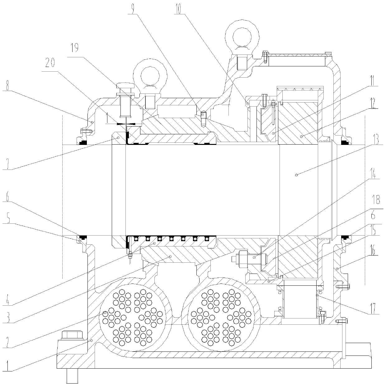
The invention provides a pedestal type radial thrust bearing device. Firstly, a stress structure of the radial thrust bearing is optimized, the shaft body dimension of a generator main shaft is adjusted, and then the pedestal type radial thrust bearing device achieves the advantages that stress is uniform, and use is reliable. Secondly, the pedestal type radial thrust bearing device adopts a novelcontact type seal ring structure, so that the design dimension of an end lid is greatly reduced, the boundary dimension of the bearing device is reduced, use is reliable, and oil splash is avoided. Finally, the pedestal type radial thrust bearing device fully considers assembly and disassembly of a water turbine generator set, by designing an auxiliary end lid, it is guaranteed that assembly anddisassembly of a thrust plate are not influenced, lightweight design is achieved at the same time, and manufacturing cost is saved.

Description

technical field [0001] The invention relates to a water turbine generator set, in particular to a seat type radial thrust bearing device. Background technique [0002] During the operation of the unit, the bearing needs to radially support the rotating parts of the hydro-generator, and at the same time bear the axial water thrust generated by the hydro-turbine. Due to the difficulty in installation and maintenance of large and medium-sized horizontal turbine units, we often set the seat type radial thrust bearing at the end of the unit near the generator to meet the needs of unit installation, but its structure often brings harm to actual processing. The shaft diameter at the end of the large shaft changes too much, which affects the stability of the main shaft of the unit and endangers the safe and stable operation of the entire unit. [0003] At present, the radial thrust bearing device of large and medium-sized horizontal turbines, in order to meet the assembly and disas...

Claims


Application Information

Patent Timeline
Patent Type & Authority Applications(China)
IPC IPC(8): F03B13/00F03B11/06F03B11/00
CPCF03B11/00F03B11/006F03B11/06F03B13/00F05B2220/706Y02E10/20
Inventor 黎宗亮
Owner 湖南云箭集团有限公司
Why Eureka
Try Eureka