Vertical type reducer

A reducer, vertical technology, applied in transmission parts, bearing components, gear transmissions, etc., can solve the problems of difficult to control gear meshing accuracy, difficult to control gear center distance, bearing drive shaft damage, etc., to reduce maintenance and maintenance. Difficulty, reduce friction, ensure the effect of axial position accuracy

Pending Publication Date: 2017-05-31
重庆腾增模具制造有限公司
View PDF10 Cites 0 Cited by
  • Summary
  • Abstract
  • Description
  • Claims
  • Application Information

AI Technical Summary

Problems solved by technology

[0002] Reducer is a common device used for gear shifting. There are many types of reducers. Most reducers are installed horizontally, that is, each transmission shaft is vertically set relative to the installation plane, because each gear shaft used for transmission is horizontal. When the vertical installation is relatively stable, the installation is relatively simple and convenient, the transmission is accurate, and the service life is long; if the transmission shaft is installed vertically, due to the influence of the self-weight of the transmission shaft and the gear itself, the installation is difficult, and the center distance between the gears is not easy. Control, and the most important thing is that the self-weight has too much friction on the end support of the transmission shaft itself. Long-term wear will easily cause damage to the bearing or the transmission shaft itself, and the meshing accuracy between the gears is also difficult to control, which is prone to gear cracking , stuck and other adverse phenomena occur

Method used


Image

  • Vertical type reducer
  • Vertical type reducer
  • Vertical type reducer

Examples


Embodiment Construction

[0034] The implementation of the present invention will be illustrated by specific specific examples below, and those skilled in the art can easily understand other advantages and effects of the present invention from the contents disclosed in this specification.

[0035] Below in conjunction with accompanying drawing and embodiment the present invention will be further described:

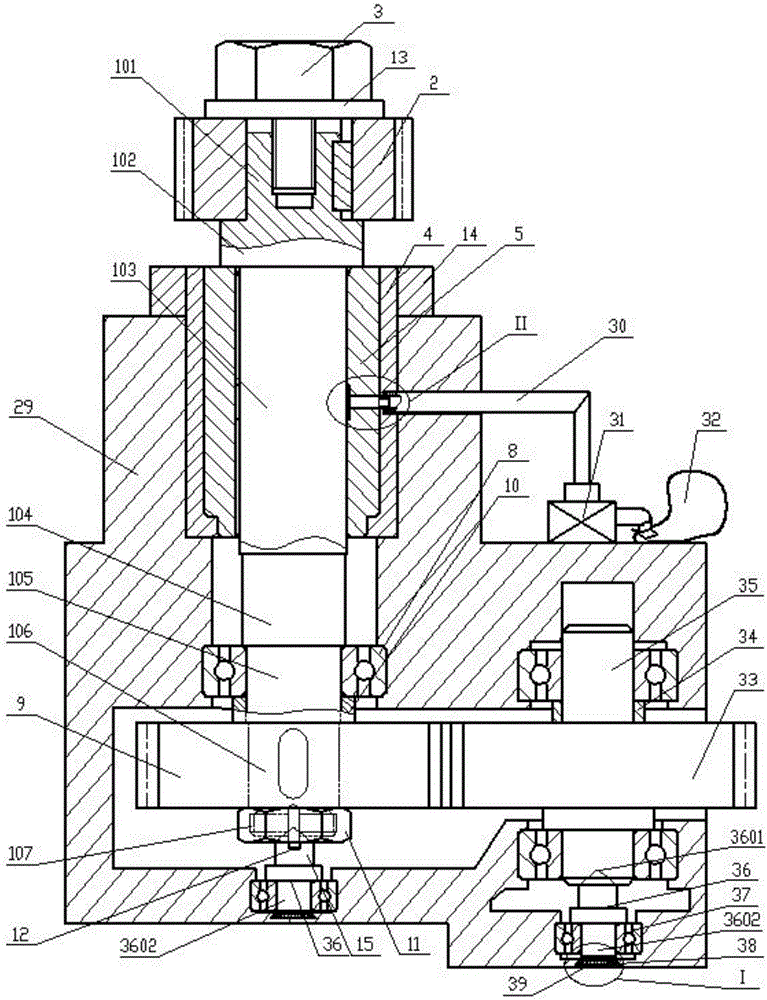
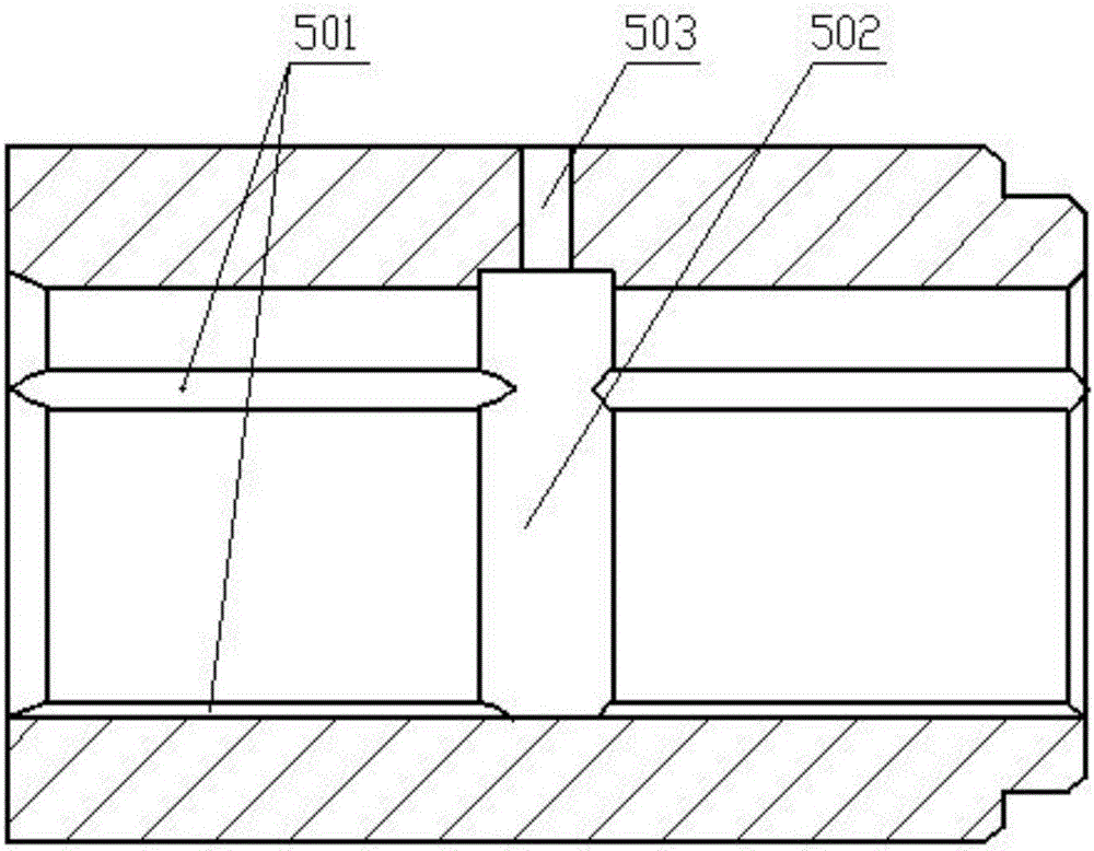
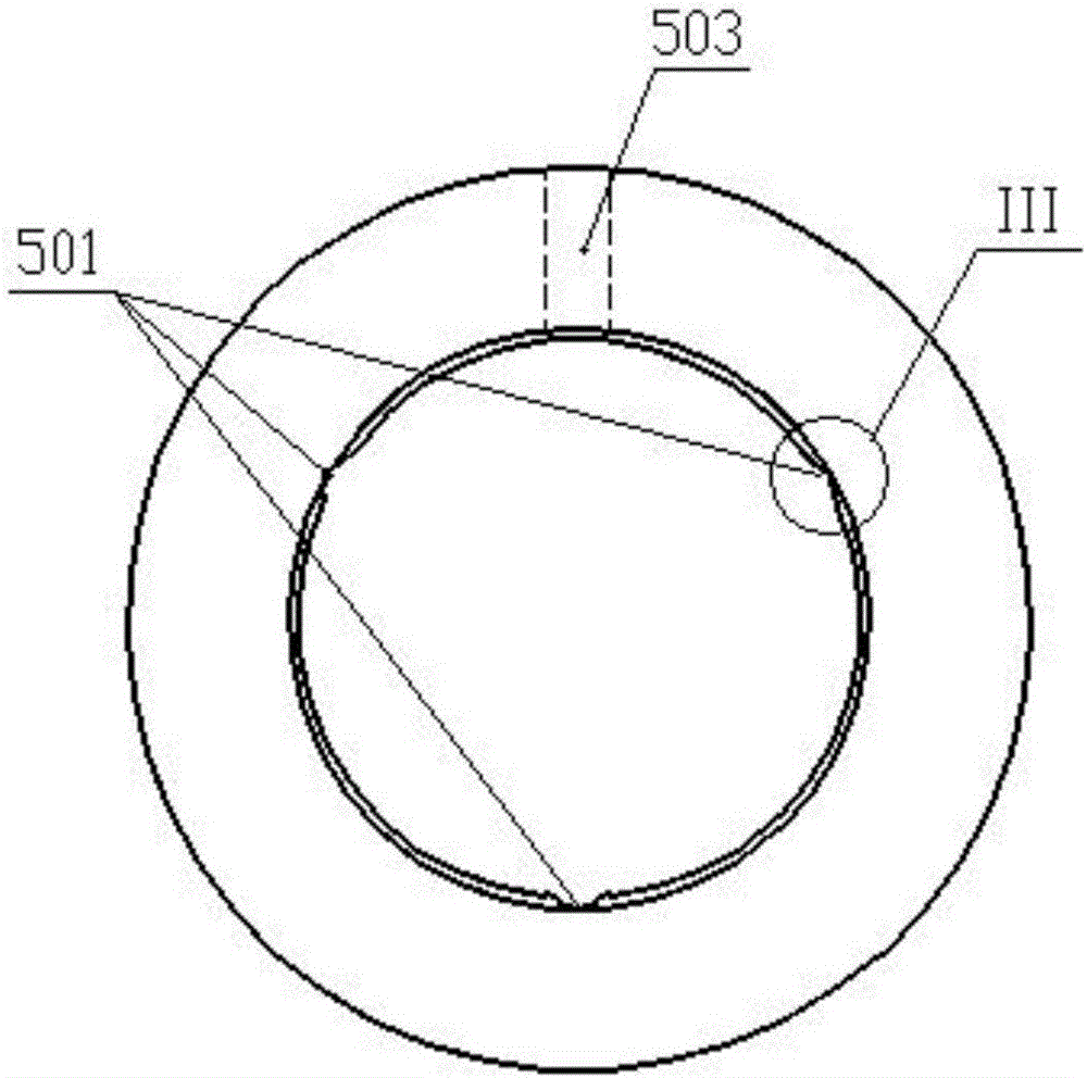
[0036] like figure 1As shown in -7, a vertical reducer includes a casing 29, which is provided with a first transmission shaft installation hole and a second transmission shaft installation hole vertically arranged in the casing 29, and the two transmission shaft installation holes are connected to each other. connected. It also includes a first vertical transmission shaft assembly located in the first transmission shaft installation hole; the first vertical transmission shaft assembly includes a vertically arranged rotating shaft 1, and the rotating shaft 1 includes sequentially connected shafts ...


PUM


Abstract

The invention discloses a vertical type reducer which comprises a case. A first vertical type transmission assembly and a second transmission shaft are arranged in the case. A first gear, a second gear and a graphite bearing assembly are arranged on the first vertical type transmission assembly. Large grooves and small grooves which mutually communicate are formed in the inner wall of a shaft hole of a graphite bearing in the axial direction. A vent hole penetrating through the graphite bearing and the hole wall of a bearing sleeve is formed in the bottoms of the large grooves. A ventilation bolt joint is arranged in a thread counter bored hole of the vent hole. The second gear and a third gear are mutually engaged, and axial jacking devices are arranged on the lower end faces of a threaded section and the second transmission shaft correspondingly. The top ends of the axial jacking devices are cones with tips, and the cones extend into the lower end faces of the first vertical type transmission assembly and the second transmission shaft. Disc springs are arranged at the bottoms of optical axis sections, and height circular pads with the thicknesses being smaller than the disc springs are arranged in the disc springs. The vertical type reducer is flexible and stable in transmission, the deflection and abrasion of the transmission shaft and striking and abrasion at the time of gear meshing due to the self weight are effectively relieved, and the speed changing accuracy is improved.

Description

technical field [0001] The invention belongs to the technical field of reducers, in particular to a reducer in which all drive shafts are vertically installed. Background technique [0002] Reducer is a common device used for gear shifting. There are many types of reducers. Most reducers are installed horizontally, that is, each transmission shaft is vertically set relative to the installation plane, because each gear shaft used for transmission is horizontal. When the vertical installation is relatively stable, the installation is relatively simple and convenient, the transmission is accurate, and the service life is long; if the transmission shaft is installed vertically, due to the influence of the self-weight of the transmission shaft and the gear itself, the installation is difficult, and the center distance between the gears is not easy. Control, and the most important thing is that the self-weight has too much friction on the end support of the transmission shaft itse...

Claims


Application Information

Patent Timeline
IPC IPC(8): F16H1/20F16H57/023F16H57/00F16C3/02F16C33/16
CPCF16C3/02F16C33/16F16H1/20F16H57/0018F16H57/023
Inventor 喻良冰
Owner 重庆腾增模具制造有限公司
Why Eureka
Try Eureka