Adjustable pipe exhaust device

An exhaust device and adjustable technology, applied in valve devices, pipe components, pipes/pipe joints/fittings, etc., can solve the problems of high suction, increase enterprise expenditure, pollution, etc., achieve long service life, increase concentration, reduce cost effect

Inactive Publication Date: 2017-05-31
THE FOURTH INST OF NUCLEAR ENG OF CNNC
View PDF8 Cites 0 Cited by
  • Summary
  • Abstract
  • Description
  • Claims
  • Application Information

AI Technical Summary

Problems solved by technology

But at the same time, because the gap is too large, there will be more air mixed in the casing 10, which will lead to a low concentration of solvent gas entering the scrubber 15, which is not conducive to the absorption of solvent tail gas.
The bushing closer to the induced draft fan 18 has higher vacuum degree, greater suction, and better exhaust effect, while the bushing farther away from the induced draft fan has a lower vacuum degree and smaller suction due to the influence of other bushings. In production practice, even the vacuum degree is 0 because the distance is too far away. When the container 13 is exhausted, the solvent tail gas will inevitably be discharged into the production workshop or the external environment, causing pollution. It is inevitable to inhale the gas in the exhaust manifold 14, causing cross-contamination between different solvents
All of the above factors have brought great inconvenience to the absorption of solvent tail gas for enterprises, increased the expenditure of enterprises, and even forced some enterprises to give up the absorption of solvent tail gas, causing pollution to the external atmospheric environment.

Method used


Image

  • Adjustable pipe exhaust device
  • Adjustable pipe exhaust device
  • Adjustable pipe exhaust device

Examples


Embodiment Construction

[0017] The present invention will be described in further detail below in conjunction with the accompanying drawings and specific embodiments.

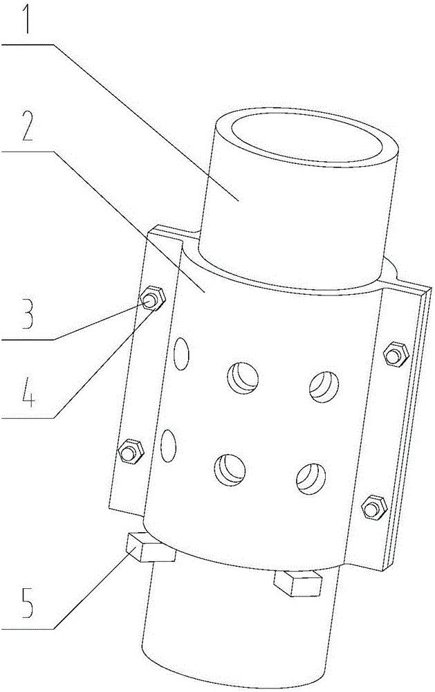
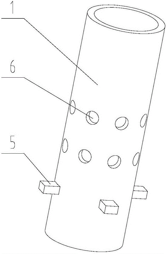
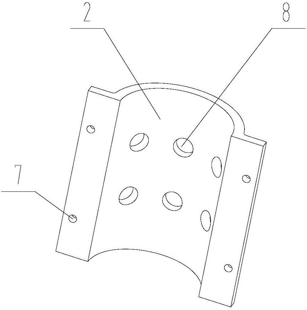
[0018] Such as Figure 1~3 As shown, an adjustable pipeline exhaust device includes an exhaust branch pipe 1, a clamp 2 and a support plate 5, wherein, the circumferential wall of the exhaust branch pipe 1 with a cylindrical cylindrical structure is provided with several pipe rows. Air holes 6, for example, can distribute several rows in the axial direction along the cylinder wall of the exhaust branch pipe 1, and evenly distribute several pipeline exhaust holes 6 along the circumferential direction; There are several support plates 5 fixed on it; the clamp 2 is two symmetrical semi-circular cylinder structures, which include a central arc-shaped surface matching the outer wall of the exhaust branch pipe 1, and an extension surface of the arc-shaped surface, and are in There is a clamp bolt hole 7 on the extension surface, and a clam...


PUM


Abstract

The invention relates to the technical field of pipe exhaust, and in particular, discloses an adjustable pipe exhaust device. The device comprises an exhaust branch pipe, a hoop and a support plate, wherein multiple pipe exhaust holes are formed in the cylinder wall of the exhaust branch pipe, and the support plate is fixed on the cylinder wall of the exhaust branch pipe below the pipe exhaust holes; the hoop is sleeved on the exhaust branch pipe, is fixedly supported by the support plate, and is provided with hoop exhaust holes; and when the hoop freely moves corresponding to the exhaust branch pipe, the areas of communicating apertures formed by the pipe exhaust holes and the hoop exhaust holes can be changed. The adjustable pipe exhaust device can largely increase the concentration of organic solvent gas entering a tail gas absorbing system; the exhaust and the inspiration between accommodating containers do not disturb each other, and the exhaust speeds are substantially equivalent, so that the enterprise solvent tail gas absorbing cost is effectively reduced, and the convenience to disassemble can be realized; and the adjustable pipe exhaust device has such advantages as simple structure, high adaptability and long service life.

Description

technical field [0001] The invention belongs to the technical field of pipeline exhaust, and in particular relates to an adjustable pipeline exhaust device. Background technique [0002] At present, organic solvents are widely used in chemical and pharmaceutical fields, and organic solvents are volatile. In order to reduce the replenishment of fresh solvents and reduce enterprise costs, most chemical and pharmaceutical companies need to absorb tail gas. The concentration of organic solvent exhaust gas in the traditional exhaust device is low, which is not conducive to the exhaust gas absorption in the later stage, and the opening between the exhaust branch pipe and the external environment cannot be adjusted, which may easily cause the container far away from the exhaust gas absorption system due to pipeline resistance, etc. The phenomenon of insufficient exhaust volume due to factors. These factors have brought great inconvenience to the absorption of organic solvent tail ...

Claims


Application Information

Patent Timeline
IPC IPC(8): F16L55/07F16K24/04
CPCF16L55/07F16K24/04
Inventor 胡福恒王绍宇窦竹洁高飞
Owner THE FOURTH INST OF NUCLEAR ENG OF CNNC
Why Eureka
Try Eureka