Separator for fuel cell, and fuel cell comprising same

A fuel cell and separator technology, which is applied to fuel cell components, fuel cells, fuel cell grouping, etc., can solve the problems of battery performance degradation, electrodes cannot provide reaction gas, and battery performance degradation, etc.

Inactive Publication Date: 2012-02-01
PANASONIC CORP
View PDF7 Cites 3 Cited by
  • Summary
  • Abstract
  • Description
  • Claims
  • Application Information

AI Technical Summary

Problems solved by technology

If generated water or condensed water stays in a specific place, the reaction gas cannot be supplied to the electrode in that area, causing a problem of degradation in battery performance (that is, flooding).
In addition, when the amount of humidification (the amount of water vapor) of the reactant gas supplied to PEFC is small (that is, when the operation is performed under low humidification conditions), there is a p

Method used


Image

  • Separator for fuel cell, and fuel cell comprising same
  • Separator for fuel cell, and fuel cell comprising same
  • Separator for fuel cell, and fuel cell comprising same

Examples


Embodiment approach 1

[0100] [Structure of fuel cell stack]

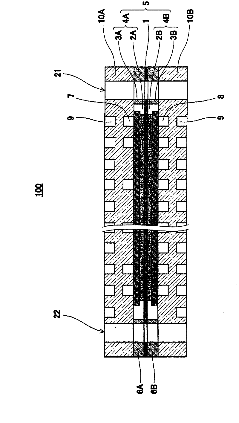
[0101] figure 1 is a cross-sectional view schematically showing the schematic structure of the fuel cell according to Embodiment 1 of the present invention. Also, in figure 1 In , a part of the fuel cell is omitted.

[0102] Such as figure 1 As shown, the fuel cell 100 according to Embodiment 1 is a single cell (cell), and includes an MEA (Membrane-Electrode-Assembly: electrolyte layer-electrode assembly) 5, gaskets 6A, 6B, an anode separator 10A, and a cathode Partition 10B.

[0103] The MEA 5 has a polymer electrolyte membrane (electrolyte layer; for example, Nafion (trade name) manufactured by DuPont, USA) 1 that selectively transports hydrogen ions, an anode 4A, and a cathode 4B.

[0104] The polymer electrolyte membrane 1 has a substantially quadrangular (here, rectangular) shape. An anode 4A and a cathode 4B (these are referred to as gas diffusion electrodes) are respectively arranged on both surfaces of the polymer electroly...

Embodiment approach 2

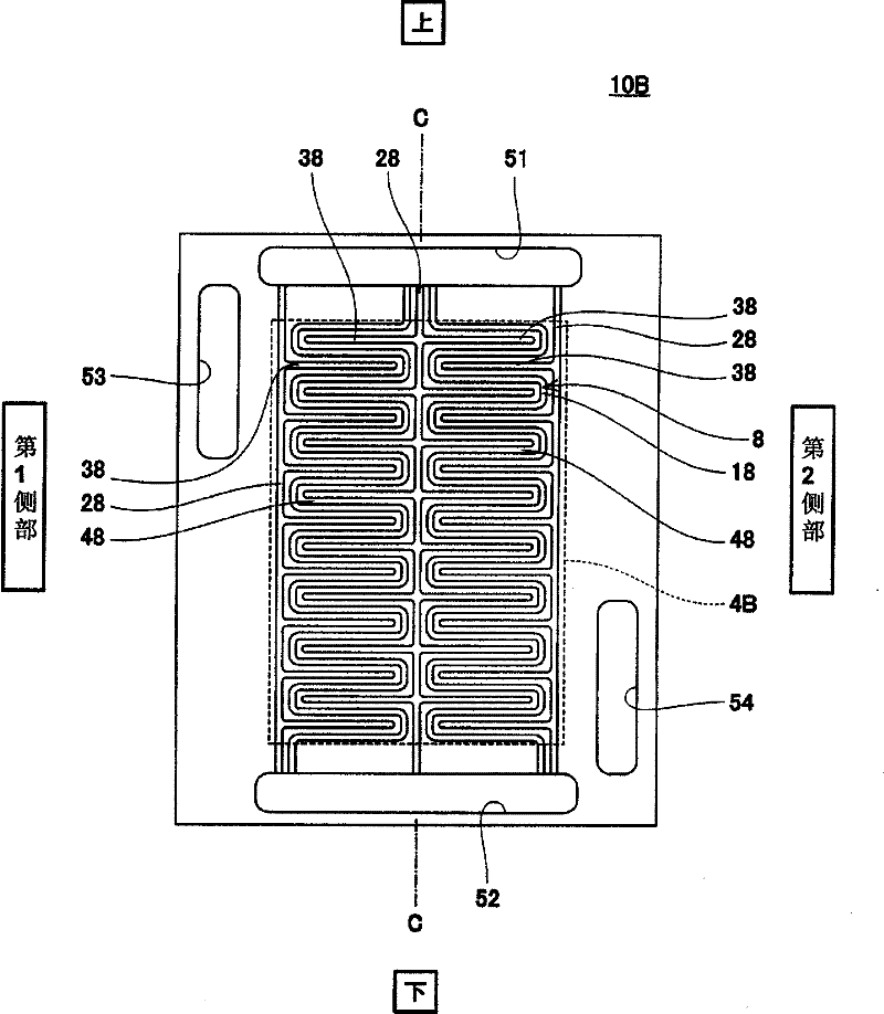
[0134] Figure 4 It is a schematic diagram showing a schematic structure of a fuel cell separator according to Embodiment 2 of the present invention.

[0135] Such as Figure 4 As shown, the fuel cell separator (cathode separator) 10B according to the second embodiment has the same basic structure as the fuel cell separator (cathode separator) 10B according to the first embodiment. In the second embodiment, the oxidizing gas flow path 8 is not provided in line symmetry with respect to the central axis C, and the shape of the first main gas flow path 18 is different from that of the first embodiment. Specifically, among the two first main gas flow paths 18, 18, the first main gas flow path 18 formed on the first side with respect to the central axis C is the same as that of the fuel cell 100 according to Embodiment 1. The cathode separator 10B is formed in the same manner. On the other hand, the first main gas passage 18 formed on the second side with respect to the central ...

Embodiment approach 3

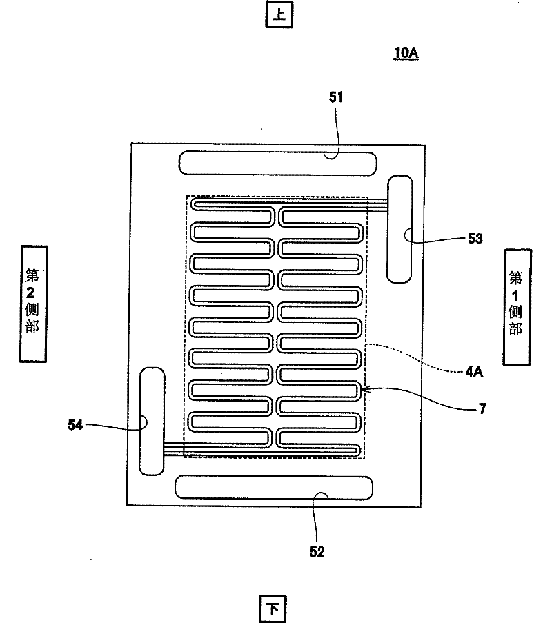
[0138] Figure 5 It is a schematic diagram showing a schematic structure of a fuel cell separator according to Embodiment 3 of the present invention.

[0139] Such as Figure 5 As shown, the fuel cell separator (cathode separator) 10B according to the third embodiment of the present invention has the same basic structure as the fuel cell separator (cathode separator) 10B according to the first embodiment. In Embodiment 3, the cross-sectional area (hereinafter simply referred to as the cross-sectional area of ​​the flow path) perpendicular to the flow of the oxidizing gas in the grooves constituting the flow path of the first assist gas flow path 28 is smaller than that of the first assist gas flow path 28 . The main gas flow path 18 and the second assist gas flow path 38 are different from the first embodiment in that the cross-sectional areas of the flow paths are formed to be small. Specifically, in Embodiment 3, the flow width of the first assist gas flow path 28 is forme...


PUM

PropertyMeasurementUnit
Proton conductivityaaaaaaaaaa

Abstract

Disclosed is a separator for fuel cells, which has a plate-like shape. The separator for fuel cells is provided with: a first gas manifold hole (51) which penetrates the separator in the thickness direction and supplies a reaction gas; a second gas manifold hole (52) which penetrates the separator in the thickness direction and discharges the reaction gas; one or more groove-like first main gas channels (18) each of which is formed on one main surface of the separator and has one end connected to the first gas manifold hole (51) and the other end connected to the second gas manifold hole (52); a groove-like first sub gas channel (28) which is formed on one main surface of the separator and has one end connected to either the first gas manifold hole (51) and/or the second gas manifold hole (52); and a groove-like second sub gas channel (38) which is formed on one main surface of the separator and has one end branched off from the first sub gas channel (28) and the other end closed.

Description

technical field [0001] The present invention relates to a fuel cell separator and a fuel cell including the same, and particularly relates to a structure of a fuel cell separator. Background technique [0002] A polymer electrolyte fuel cell (hereinafter referred to as PEFC) is a device that simultaneously generates electricity and heat by electrochemically reacting a hydrogen-containing fuel gas with an oxygen-containing oxidant gas such as air. A PEFC single cell (cell) has an MEA (Membrance-Electrode-Assembly: Membrane-Electrode-Assembly) consisting of a polymer electrolyte membrane and a pair of gas diffusion electrodes (anode and cathode), a gasket, and a conductive plate-shaped separator. plate. In addition, PEFC is generally formed by stacking a plurality of single cells, sandwiching both ends of the stacked single cells with end plates, and connecting the end plates and the single cells with a connecting tool. [0003] However, when the polymer electrolyte membrane...

Claims


Application Information

Patent Timeline
IPC IPC(8): H01M8/02H01M8/24H01M8/10
CPCH01M8/0258Y02E60/50H01M2008/1095H01M8/04119H01M8/0247H01M8/0263H01M8/2483H01M8/0267H01M8/026
Inventor 竹口伸介中川贵嗣辻庸一郎
Owner PANASONIC CORP
Why Eureka
Try Eureka