Double-temperature double-compressor water cooling unit and refrigerating control method thereof
A technology of dual compressors and water chillers, applied in the direction of compressors, compressors with cascading work, refrigerators, etc., can solve the problems of limited heat exchange effect of evaporators, complex structure, and inability to adjust, so as to achieve energy saving effect Significant, simple device structure, and the effect of reducing reheat loss
- Summary
- Abstract
- Description
- Claims
- Application Information
AI Technical Summary
Problems solved by technology
Method used
Image

Examples
Embodiment 1
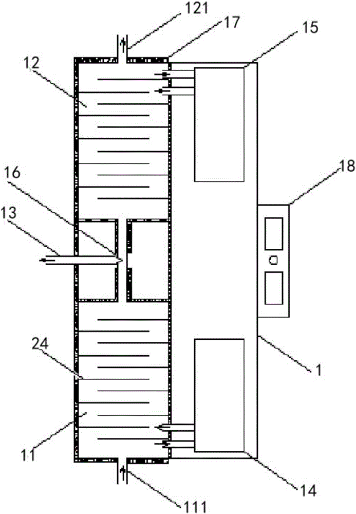
[0032] Such as figure 1As shown, the dual-temperature dual-compressor water chiller of the present invention includes a unit housing 1 with an inner cavity, and the unit housing 1 is composed of a cooling housing 2 of a high-temperature shell-and-tube heat exchange device 11 and a low-temperature shell-and-tube heat exchange device The refrigerating shells 2 of 12 are butted with each other, and the unit shell 1 is provided with an insulation layer 17 on the outside of the circumference. The water outlet 111 communicates with the high-temperature shell-and-tube heat exchange device 11 in the casing 1 of the unit, and the low-temperature water outlet 121 communicates with the low-temperature shell-and-tube heat exchange device 12 in the unit. Between the shell-and-tube heat exchange devices 12, there is a switching structure that enables the high-temperature shell-and-tube heat exchange device 11 to communicate with the low-temperature shell-and-tube heat exchange device 12 and...
Embodiment 2
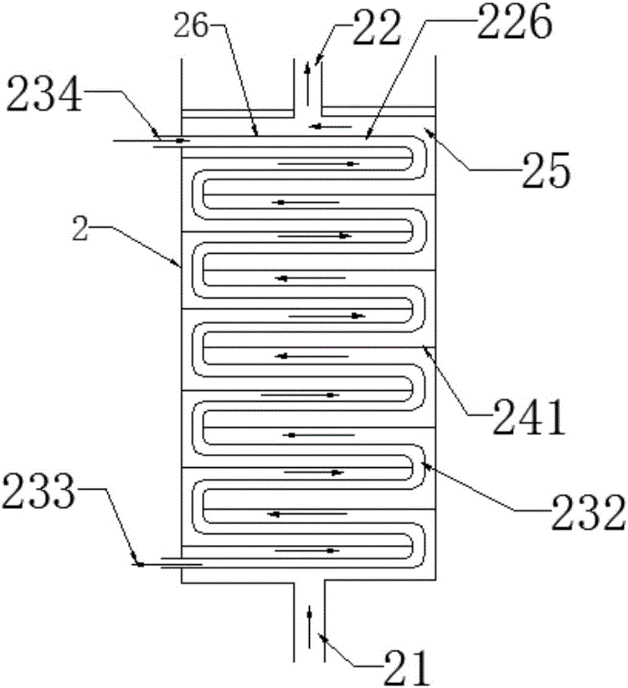
[0044] Such as image 3 As shown, this embodiment is similar to Embodiment 1, the difference is that the heat transfer tube bundle 23 in this embodiment is arranged in a transverse bend in the refrigeration housing 2, and the heat transfer tube bundle 23 includes a lateral extension 26 and an arc The curved portion 232 and the lateral extension portion 26 are arranged horizontally from top to bottom and parallel to the baffle 241 , and in this embodiment, the two sides of the baffle 241 are respectively fixed to the arc-shaped curved portion 232 and the refrigeration housing On the inner wall of 2, the baffle plate 241 from top to bottom is misplaced to guide the water source medium so that the water source medium flows from the cold water inlet 21 to the cold water outlet 22 along the heat transfer tube bundle, and in this embodiment, the cooling The flow direction of the agent is from top to bottom, that is, from the lateral extension closest to the cold water outlet 22 to t...
PUM
 Abstract
Description
Claims
Application Information
PatSnap Eureka turns technology decisions into work you can execute. Powered by our Innovation Knowledge Graph, it runs expert workflows across engineering, life sciences, materials and intellectual property. Get your review-ready output in minutes.


