Pseudo-triaxial test device based on dynamic fatigue testing machine

A dynamic fatigue and testing device technology, applied in measuring devices, using stable tension/pressure to test material strength, instruments, etc., to achieve the effects of high control accuracy, complete protection functions, and strong anti-pollution capabilities

Active Publication Date: 2017-05-31
PLA UNIV OF SCI & TECH
View PDF5 Cites 3 Cited by
  • Summary
  • Abstract
  • Description
  • Claims
  • Application Information

AI Technical Summary

Problems solved by technology

Conventional triaxial rock mechanics tests generally apply a certain confining pressure to the rock, and then keep the confining pressure constant (that is, σ2 = σ3) to increase the maximum princip

Method used


Image

  • Pseudo-triaxial test device based on dynamic fatigue testing machine
  • Pseudo-triaxial test device based on dynamic fatigue testing machine
  • Pseudo-triaxial test device based on dynamic fatigue testing machine

Examples


Embodiment 1

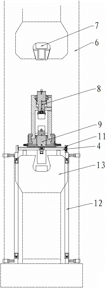
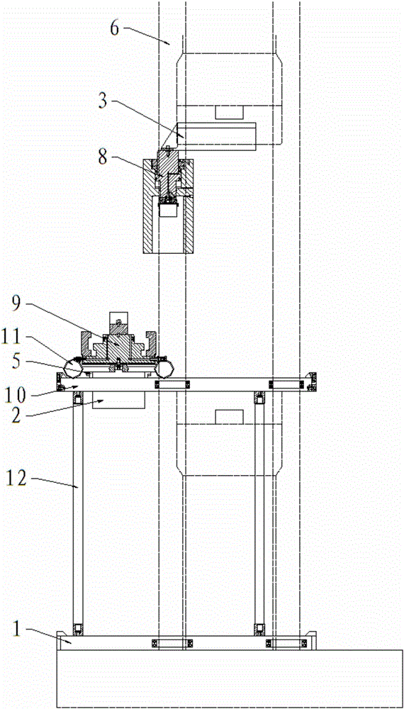
[0028] This embodiment provides a pseudo-triaxial testing device based on a dynamic fatigue testing machine, the structure of which is as follows: figure 1 , figure 2 As shown, including the column 6, the upper and lower ends of the column 6 are respectively provided with an upper hydraulic chuck and a lower hydraulic chuck 13, the upper hydraulic chuck is connected to the upper end of the upper pressure column 7, and the lower end of the upper pressure column 7 is connected to the upper connection block 3, The lower end of the upper connection block 3 is fixedly equipped with a pressure chamber main body 8, and the pressure chamber base 9 is correspondingly provided below the pressure chamber main body 8, and the pressure chamber base 9 is fixedly installed on the trolley, and at least two square axles 4 and square axle 4 Wheels 11 are respectively installed at both ends, and the wheels 11 are arranged on the guide rail 10, and the guide rail 10 is horizontally installed in ...

Embodiment 2

[0032] The present embodiment provides a pseudo-triaxial test method based on a dynamic fatigue testing machine, comprising the following specific steps:

[0033] Step (1), assemble the sample into a sample assembly as required;

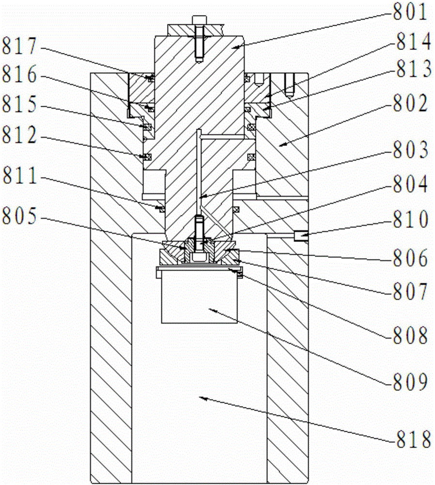
[0034] Step (2), install the cushion block on the pressure chamber base 9, and then place the sample assembly on the cushion block, the cushion block includes the first cushion block 901 and the second cushion block 902, and the pressure chamber base 9, the first cushion block The column pin 903 is used for connection and positioning between the block 901 and the second pad 902, and the total height of the "pad + sample assembly + upper pad 809 + joint bearing seat" is not 290 ± 20mm, and the joint bearing seat includes The cushion cover 805, the outer spherical body 806 and the inner spherical body 807 are installed sequentially from the inside to the outside;

[0035] Step (3), hoist the main body 8 of the pressure chamber on the base 9 of the pre...


PUM


Abstract

The invention discloses a pseudo-triaxial test device based on a dynamic fatiguetesting machine. The device comprises a stand column, wherein an upper hydraulic chuck and a lower hydraulic chuck are correspondingly arranged on the upper end and the lower end of the stand column; the upper hydraulic chuck is connected to the upper end of an upper pressure-transmitting column; the lower end of the upper pressure-transmitting column is connected with an upper connecting block; a pressure chamber main body is fixedly arranged on the lower end of the upper connecting block; a pressure chamber base is correspondingly arranged under the pressure chamber main body, and is fixedly arranged on a trolley; a lower connecting block is arranged under the trolley, is fixedly arranged on the trolley through a connecting plate, and is connected with the lower hydraulic chuck. According to the device designed by the invention, equipment is refitted on the basis of the dynamic fatigue testing machine, so that an elastic parameter of a rock can be measured, and a strain test, a creep test and a relaxation test are finished at different confining pressures, and a flow parameter of a stratum is tested, and the breaking tenacity of the rock and the in-situ stress of the stratum are tested under a simulated in-situ stress level.

Description

technical field [0001] The invention belongs to the technical field of rock pseudo-triaxial testing equipment, and relates to a pseudo-triaxial testing device based on a dynamic fatigue testing machine. Background technique [0002] Under natural conditions, the crust and engineering rock mass are deformed and destroyed under complex combined stress states. Rock mass is a complex geological body, which is in a complex three-dimensional stress field, and the failure of rock mass is usually caused by the change of its existing stress state. Conventional triaxial rock mechanics tests generally apply a certain confining pressure to the rock, and then keep the confining pressure constant (that is, σ2 = σ3) to increase the maximum principal stress σ1 to cause rock damage. This test method can only study axisymmetric stress State, not applicable to the influence of intermediate principal stress on rock mass strength and deformation. Contents of the invention [0003] The techni...

Claims


Application Information

Patent Timeline
IPC IPC(8): G01N3/10G01N3/04
CPCG01N3/04G01N3/10G01N2203/0075G01N2203/0071G01N2203/0019G01N2203/0003G01N2203/0048G01N2203/0682G01N2203/0676Y02E30/30
Inventor 马林建王明洋张宁范鹏贤吕亚茹阳发董璐
Owner PLA UNIV OF SCI & TECH
Why Eureka
Try Eureka