Optical-fiber dust concentration measurement apparatus

A dust concentration and measuring device technology, which is applied in the direction of measuring devices, suspension and porous material analysis, scientific instruments, etc., can solve the problems of measurement delay difference, poor safety, and affecting measurement accuracy, so as to eliminate measurement errors and improve unfavorable Influence, facilitate the effect of optical fiber transmission

Active Publication Date: 2017-05-31
XIAN UNIV OF SCI & TECH
View PDF10 Cites 8 Cited by
  • Summary
  • Abstract
  • Description
  • Claims
  • Application Information

AI Technical Summary

Problems solved by technology

[0003] Existing hand-held dust concentration measurement devices must require operators to measure on the spot, and in environments with high dust concentrations similar to coal mines, operators must take dust-proof measures when measuring, otherwise it will damage the respiratory tract and affect health
The existing chemical reaction type dust concentration sensor needs to collect and process the air dust, which has a measurement delay difference and cannot perform real-time measurement; the electric dust concentration measurement device has poor safety. When the mine dust concentration is too high, a slight Sparks raise risk of mine explosion
For the fiber-optic dust concentration sensor, the optical fiber is used to transmit the optical signal over a long distance, and remote measurement can be realized. However, the measuring instrument is located in a high-dust area.

Method used


Image

  • Optical-fiber dust concentration measurement apparatus
  • Optical-fiber dust concentration measurement apparatus
  • Optical-fiber dust concentration measurement apparatus

Examples


Embodiment Construction

[0031] The technical solutions in the embodiments of the present invention will be clearly and completely described below in conjunction with the drawings in the present invention. Apparently, the described embodiments are only some of the embodiments of the present invention, not all of them. Based on the embodiments of the present invention, all other embodiments obtained by persons of ordinary skill in the art without making creative efforts belong to the protection scope of the present invention.

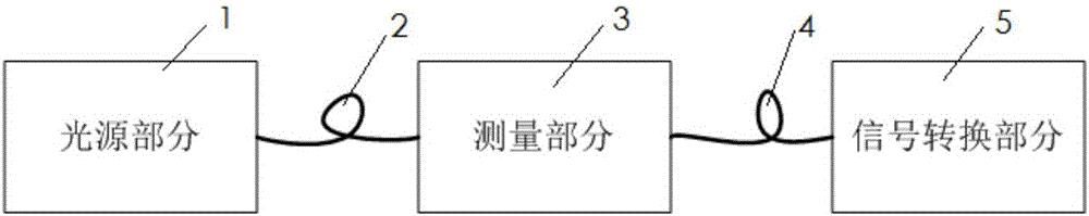
[0032] Such as figure 1 As shown, the fiber-optic dust concentration measuring device of the first embodiment of the present invention includes a light source part 1, an input fiber 2, a measurement part 3, an output fiber 4 and a signal conversion part 5, and the light source part 1 and the measurement part 3 pass through the input fiber 2 connection, the measurement part 3 and the signal conversion part 5 are connected through the output optical fiber 4, and the connection met...


PUM


Abstract

The invention relates to the technical field of dust concentration measurement, and particularly discloses an optical-fiber dust concentration measurement apparatus. The optical-fiber dust concentration measurement apparatus successively comprises a light source part, an input optical fiber, a measurement part, an output optical fiber, a signal conversion part and a data processing part. The measurement part comprises a beam splitter, a first measurement area consisting of a first transmitting end, a first attenuation area, a first receiving end and a first connecting rod, and a second measurement area consisting of a second transmitting end, a second attenuation area, a second receiving end and a second connecting rod. Laser is divided by the beam splitter into a first optical path and a second optical path and then enters the first measurement area and the second measurement area to be measured, and after the measurement, an optical signal is outputted by virtue of the output optical fiber to the signal conversion part to be converted into an electric signal, and the data processing part calculates a laser attenuation coefficient by virtue of the received electric signal. By utilizing the dual-optical-path measurement and differential operation method, a measurement error is eliminated, and the measurement precision is improved.

Description

technical field [0001] The invention relates to the field of dust concentration measurement, in particular to an optical fiber type dust concentration measurement device. Background technique [0002] The measurement methods of dust concentration mainly include optical analysis method and non-optical analysis method. Due to the slow response speed of detection equipment and complicated processing, non-optical analysis method is difficult to monitor the dust concentration in real time. The dust concentration measurement technology based on optical analysis has the characteristics of high detection sensitivity, strong selectivity, and fast response speed. It is suitable for on-site real-time monitoring, and the cost is low. It is an ideal method for dust concentration measurement in the future. [0003] Existing hand-held dust concentration measuring devices must require operators to measure on site, and in environments with high dust concentrations similar to coal mines, oper...

Claims


Application Information

Patent Timeline
Patent Type & Authority Applications(China)
IPC IPC(8): G01N15/06
CPCG01N15/06G01N2015/0693
Inventor 刘海强
Owner XIAN UNIV OF SCI & TECH
Why Eureka
Try Eureka