Reflective optical fiber dust concentration measuring system

A dust concentration and measurement system technology, applied in the direction of measurement devices, suspension and porous material analysis, climate sustainability, etc., can solve the problems of measurement delay difference, poor safety, and affecting measurement accuracy, and achieve the elimination of measurement errors, Effects of improving adverse effects and improving measurement accuracy

Active Publication Date: 2017-05-31
XIAN UNIV OF SCI & TECH
View PDF8 Cites 8 Cited by
  • Summary
  • Abstract
  • Description
  • Claims
  • Application Information

AI Technical Summary

Problems solved by technology

[0003] Existing hand-held dust concentration measuring devices must require operators to measure on the spot, and in environments with high dust concentrations such as coal mines, operators must take dust-proof measures when measuring, otherwise it will damage the respiratory tract and affect health
The existing chemical reaction type dust concentration sensor needs to collect and process the air dust, which has a measurement delay difference and cannot perform real-time measurement; the electric dust concentration measurement device has poor safety. When the mine dust concentration is too high, a slight Sparks raise risk of mine explosion
For the fiber-optic dust concentration sensor, the optical fiber is used to transmit the optical signal over a long distance, which can realize remote measurement, but the measuring instrument is located in a high-dust area. Loss, so that the transmission effect of the laser is affected, which in turn affects the measurement accuracy

Method used


Image

  • Reflective optical fiber dust concentration measuring system
  • Reflective optical fiber dust concentration measuring system
  • Reflective optical fiber dust concentration measuring system

Examples


Embodiment Construction

[0031] The technical solutions in the embodiments of the present invention will be clearly and completely described below in conjunction with the drawings in the present invention. Apparently, the described embodiments are only some of the embodiments of the present invention, not all of them. Based on the embodiments of the present invention, all other embodiments obtained by persons of ordinary skill in the art without making creative efforts belong to the protection scope of the present invention.

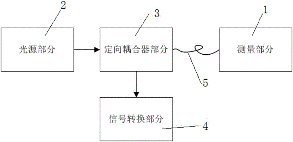
[0032] Such as figure 1 As shown, a reflective optical fiber dust concentration measurement system according to the first embodiment of the present invention includes a measurement part 1, a light source part 2, a directional coupler part 3, a signal conversion part 4, a light source part 2, and a signal conversion part 4 Respectively connected to the directional coupler part 3, the measurement part 1 and the directional coupler part 3 are connected through an optical fiber 5, a...


PUM


Abstract

The invention relates to the technical field of dust concentration measurement, and concretely discloses a reflective optical fiber dust concentration measuring device. The reflective optical fiber dust concentration measuring device comprises a measuring part, a light source part, a directional coupler part and a signal conversion part, wherein the measuring part comprises a laser regulating end, an attenuation region and a reflecting end; the light source part generates laser and transmits the laser to the directional coupler part; the directional coupler part transmits the laser to the measuring part through optical fiber; after entering the measuring part, the laser is firstly regulated through the laser regulating end, then enters the attenuation region to perform attenuation measurement, and is vertically incident into the reflecting end; the reflecting end reflects the laser; the laser sequentially passes through the attenuation region and the laser regulating end, and is then transmitted back to the directional coupler part by the optical fiber; the directional coupler part transmits the reflected laser to the signal conversion part. The optical fiber is used for transmitting an optical signal; the remote measurement is realized; the measuring part is a pure optical device; high safety is realized when the device is arranged in a measuring region with high dust concentration.

Description

technical field [0001] The invention relates to the field of dust concentration measurement, in particular to a reflective optical fiber dust concentration measurement system. Background technique [0002] The measurement methods of dust concentration mainly include optical analysis method and non-optical analysis method. Due to the slow response speed of detection equipment and complicated processing, non-optical analysis method is difficult to monitor the dust concentration in real time. The dust concentration measurement technology based on optical analysis has the characteristics of high detection sensitivity, strong selectivity, and fast response speed. It is suitable for on-site real-time monitoring, and the cost is low. It is an ideal method for dust concentration measurement in the future. [0003] Existing hand-held dust concentration measuring devices must require operators to measure on the spot, and in environments with high dust concentrations such as coal mines...

Claims


Application Information

Patent Timeline
Patent Type & Authority Applications(China)
IPC IPC(8): G01N15/06
CPCG01N15/06G01N2015/0693Y02A90/10
Inventor 刘海强
Owner XIAN UNIV OF SCI & TECH
Why Eureka
Try Eureka