
AOI (Automated Optical Inspection)-based macroscopic defect detection device and method

A macro-defect and detection device technology, applied in the direction of optical testing flaws/defects, etc., can solve problems such as inability to deal with uneven color, inability to photograph, inability to collect color information, etc., to achieve the effect of enriching types and capabilities

Active Publication Date: 2017-05-31
WUHAN JINGCE ELECTRONICS GRP CO LTD
View PDF3 Cites 39 Cited by
  • Summary
  • Abstract
  • Description
  • Claims
  • Application Information

AI Technical Summary

Problems solved by technology

The above methods mainly have the following problems: 1) Unable to deal with the defects of uneven color Since the camera used is a single-channel grayscale camera, which cannot collect color information, it cannot detect such defects
2) Unable to deal with defects that are visible from a squint angle Some defects, especially some mura defects, are invisible from a front view angle, so it cannot be captured by a front view camera, let alone detected in the captured image
3) The ability to detect large-area defects Even for some defects that are visible when viewed directly, due to their relatively large area, it will be very time-consuming to detect these defects on high-resolution images
In addition, the resolution of high-resolution images (the resolution of the camera's CCD and the resolution of the LCD) is often 3:1, so the captured image itself has texture information. When removing these texture information, it is likely to also Removed the relatively weak Mura defect

Method used


Image

  • AOI (Automated Optical Inspection)-based macroscopic defect detection device and method
  • AOI (Automated Optical Inspection)-based macroscopic defect detection device and method
  • AOI (Automated Optical Inspection)-based macroscopic defect detection device and method

Examples


Embodiment Construction

[0057] The present invention will be further described in detail below in conjunction with the accompanying drawings and specific embodiments to facilitate a clear understanding of the present invention, but they do not limit the present invention.

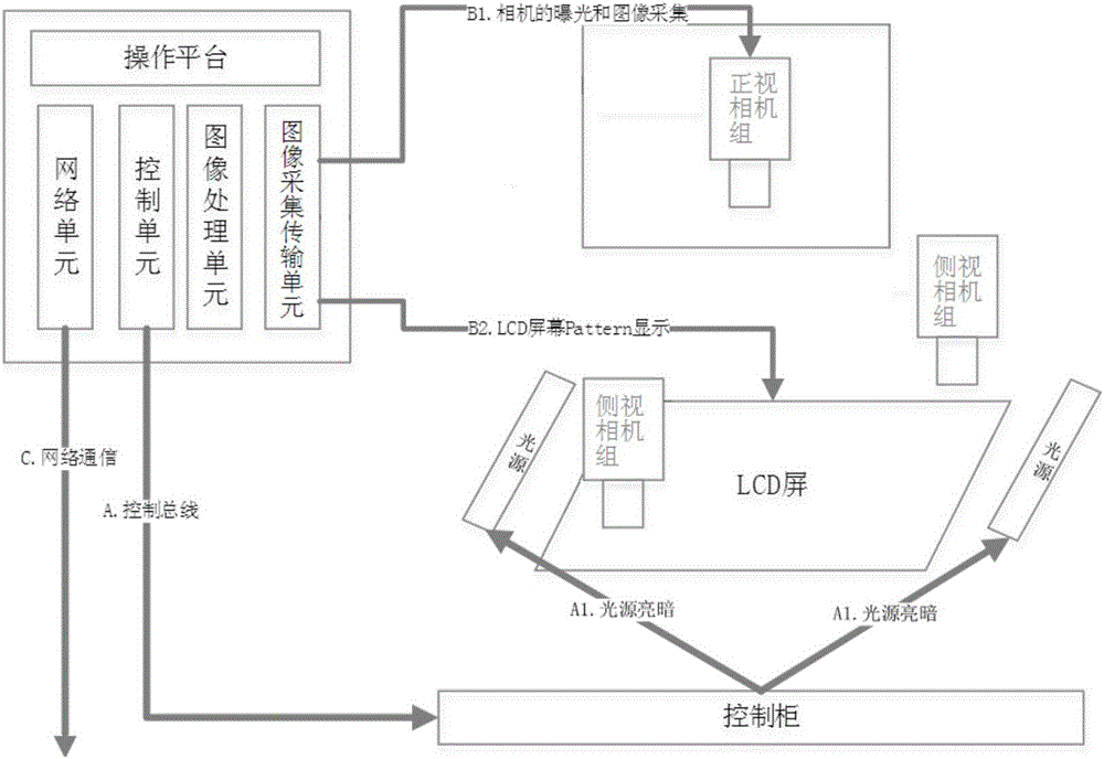
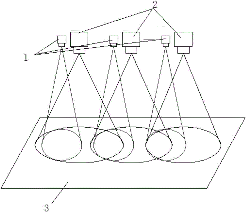
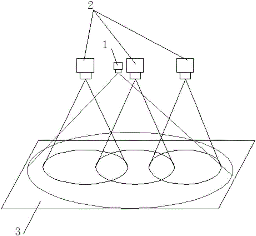
[0058] Such as figure 1 As shown, the present invention provides an AOI-based macroscopic defect detection device, which is characterized in that it includes a system platform, an LCD screen, a light source, a control cabinet, a front-view camera group, and at least two groups of side-view camera groups that are arranged symmetrically; The system platform includes a network unit, a control unit, an image processing unit, and an image acquisition and transmission unit; the light source is evenly distributed around the LCD screen, and the particle image on the LCD screen is supplemented with light, so that the dust on the LCD panel can be accurately and completely photographed ; The front-facing camera group and the side-view camera...


PUM


Abstract

The invention provides an AOI (Automated Optical Inspection)-based macroscopic defect detection device used for detecting macroscopic display defects of a flat panel display module. The macroscopic defect detection device comprises a light source, a camera group, and an image acquisition and processing unit interacting with the camera group, and is characterized in that the camera group comprises at least one group of front view camera components and at least two groups of symmetrically arranged side view camera components, wherein the front view camera components and the side view camera components are positioned above a to-be-detected display panel and are used for photographing display images of the to-be-detected display panel; the photographing angle of the front view camera group is perpendicular to the to-be-detected display panel; an included angle exists between the photographing angle of the side view camera group and the to-be-detected display panel; and the to-be-detected display panel is positioned in a photographing range of the front view camera group and the side view camera group. According to the macroscopic defect detection device disclosed by the invention, the defects during defect detection by industrial front view cameras are overcome, and the type and capability of AOI defect detection are greatly enriched.

Description

technical field [0001] The invention belongs to the field of AOI LCD / OLED defect automatic detection, and in particular relates to an AOI-based macroscopic defect detection device and method. Background technique [0002] Due to the complexity of the production process of LCD and OLED, each process will introduce some display defects, and the differences of these defects are very large. [0003] For some fine microscopic display defects, such as bright (dark) points and bright (dark) lines, they can be photographed and processed by low-noise industrial cameras. However, some defects have relatively large areas, and may be manifested in color differences or uneven brightness. In addition, there are many defects that are not visible under the front view angle. For such macroscopic defects, pictures taken by ordinary low-noise industrial cameras cannot be detected. For AOI LCD / OLED defect detection, in the existing technical solutions, it is mainly to use low-noise, high-res...

Claims


Application Information

Patent Timeline
Patent Type & Authority Applications(China)
IPC IPC(8): G01N21/95
CPCG01N21/95
Inventor 张胜森张力邓标华陈凯沈亚非
Owner WUHAN JINGCE ELECTRONICS GRP CO LTD
Learn More