Light guide plate

A light guide plate and technology in the light guide plate, applied in the field of light guide plates, can solve the problems of reducing equipment endurance, waste, and user reception, and achieve the effects of simple structure, improved utilization rate, and reduced power consumption

Pending Publication Date: 2017-05-31
SHENZHEN BAOMING TECH
View PDF0 Cites 0 Cited by
  • Summary
  • Abstract
  • Description
  • Claims
  • Application Information

AI Technical Summary

Problems solved by technology

Under normal circumstances, the user faces the device itself in the process of using it. When the brightness needs to be adjusted, the brightness can only be increased by increasing the luminous intensity. However, in practice, the power consumption of the backlight source is often the most power consumption of the device. In the serious part, increasing the luminous intensity will reduce the battery life of the device; on the other hand, the light emitted by the backlight source is emitted in all directions through the light-transmitting surface, and a large part of the light cannot be received by the user, resulting in waste

Method used


Image

  • Light guide plate
  • Light guide plate

Examples


Embodiment 1

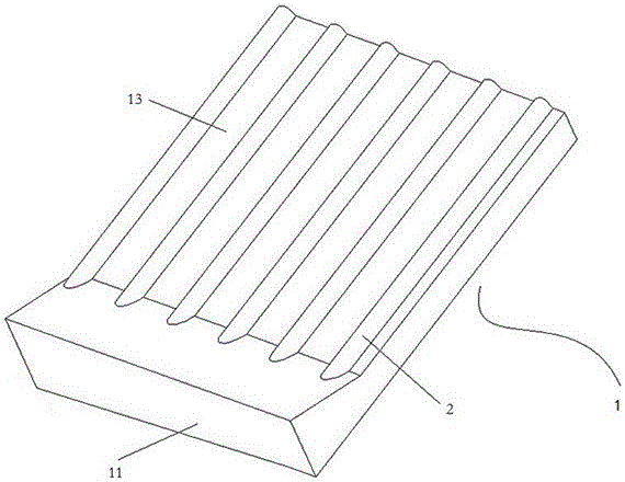
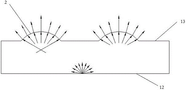
[0026] as attached figure 1 And attached figure 2 As shown, the bottom of the light guide plate 1 is the incident surface 11 , and by disposing the light source on the edge of the incident surface 11 , the light emitted by the light source can enter the interior of the light guide plate 1 through the incident surface 11 . Both sides, the top and the bottom of the light guide plate 1 are reflective surfaces 12, and the reflective surface 12 can reflect the light irradiated on the surface at a certain angle. The upper part of the light guide plate 1 is a light-transmitting surface, and the light-transmitting surface can allow internal light to pass through.

[0027] A plurality of strip-shaped arc-shaped protrusions, ie light-concentrating structures 2 , are arranged on the light-transmitting surface. Different light-concentrating structures 2 are arranged longitudinally at equal distances, and the distance between the light-concentrating structures 2 is 150 μm. The height of...


PUM

PropertyMeasurementUnit
Arc radiusaaaaaaaaaa
Bump heightaaaaaaaaaa

Abstract

The invention discloses a light guide plate. The light guide plate comprises an incidence face, reflection faces and an outgoing face, wherein the incidence face is arranged on one side of the light guide plate and is used for introducing a light source; the outgoing face is arranged on the upper surface of the light guide plate and is used for enabling light to be transmitted outward from the inner part of the light guide plate; the reflection faces are arranged on the other surfaces except the incidence face and the outgoing face on the light guide plate and are used for limiting the light in the light guide plate; and the outgoing face is provided with an outward convex light condensation structure. The light condensation structure is arranged on the outgoing face, and then the light, which is not received by a user before, is gathered to an angle range capable of being received by the user, so that the light utilization rate is improved and the loss of energy is reduced; the light guide plate also has the characteristic of moderate imaging effect, and other structures in a backlight module are also not influenced; and the light guide plate has good utilization effects and obvious economic benefits.

Description

technical field [0001] The invention relates to the field of liquid crystal displays (Liquid Crystal Display, LCD), in particular to a light guide plate in an LCD backlight module. Background technique [0002] In LCD imaging, because the liquid crystal itself does not emit light, the backlight unit (BLU) placed under the LCD needs to provide a backlight light source. After the bottom light source emits light, it passes through the upper liquid crystal to produce different images. Under normal circumstances, the user faces the device itself in the process of using it. When the brightness needs to be adjusted, the brightness can only be increased by increasing the luminous intensity. However, in practice, the power consumption of the backlight source is often the most power consumption of the device. In the serious part, increasing the luminous intensity will reduce the battery life of the device; on the other hand, the light emitted by the backlight source is emitted in all ...

Claims


Application Information

Patent Timeline
IPC IPC(8): G02B6/00G02F1/13357
CPCG02B6/0013G02B6/0035G02F1/133606G02F1/133607
Inventor 焦江华张春
Owner SHENZHEN BAOMING TECH
Why Eureka
Try Eureka