Supercharge Your Innovation With Domain-Expert AI Agents!

Method of positioning object under observation under microscope

A microscope and microscope technology, applied in microscopes, optics, instruments, etc., to improve positioning efficiency, reduce the frequency of adjusting the focus, and facilitate production

Inactive Publication Date: 2017-05-31
SOUTH WEST INST OF TECHN PHYSICS
View PDF1 Cites 1 Cited by
  • Summary
  • Abstract
  • Description
  • Claims
  • Application Information

AI Technical Summary

Problems solved by technology

[0005] The purpose of the present invention is to propose a method for quickly locating the observed object under a microscope to solve the problem of how to quickly locate the observed object on the carrier

Method used


Image

  • Method of positioning object under observation under microscope

Examples


Embodiment Construction

[0018] In order to make the purpose, content, and advantages of the present invention clearer, the specific implementation manners of the present invention will be further described in detail below in conjunction with the accompanying drawings and embodiments.

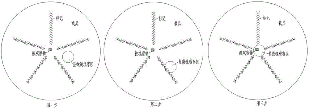
[0019] The embodiment of the present invention proposes a method for rapidly locating the observed object under a microscope, such as figure 1 As shown, the method includes the following steps:

[0020] Make multiple directional marks on the carrier used to carry the object to be observed. The carrier is filter paper or glass slide. The mark is a line segment composed of multiple arrow symbols. The arrows in the mark all point to the carrier for The location of the object under observation;

[0021] Place the observed object on the specified position on the carrier, and place the carrier under the microscope to adjust the focal length of the microscope observation area;

[0022] Move the carrier arbitrarily until the...


PUM


Abstract

The invention belongs to the field of microscopic detection and particularly relates to a method of positioning an object under observation under a microscope; the method comprises: making multiple directional markers on a carrier that serves for carrying an object under observation, wherein each marker points to a position on the carrier for bearing the object under observation; placing the object under observation in position on the carrier, and placing the carrier under the microscope; moving the carrier until the corresponding marker is viewed in the field of the microscope; moving the carrier according to the pointing of the marker until the object under observation is viewed in the field of the microscope. By using the method, it is possible to quickly position an object under observation in the limited visual field of a microscope, particularly a high-power microscope, positioning efficiency is improved, the frequency of adjusting focal length in observation is decreased, and eye usage health of an observer is improved.

Description

technical field [0001] The invention belongs to the field of microscopic detection, and in particular relates to a method for quickly locating an observed object under a microscope. Background technique [0002] When using a microscope for observation in the prior art, there is a problem that the field of view of the microscope is narrow and the search area is large, and it is difficult to locate the object to be observed. Taking a stereo microscope as an example, at a magnification of 40 times, the field of view in the eyepiece is about φ2mm, and a φ90mm filter paper is used as a carrier, and the area ratio of the two is 1:2025. In fact, when placing the observed object, it can generally be placed at the center of the field of view φ40mm, and its area ratio is also 1:400. If you only rely on the mobile vehicle, trying to find the observed object within the field of view of the eyepiece is tantamount to "finding a needle in a haystack". [0003] In addition, the commonly u...

Claims


Application Information

Patent Timeline
Patent Type & Authority Applications(China)
IPC IPC(8): G02B21/34
CPCG02B21/34
Inventor 黄海华向秋澄刘期斌何伟
Owner SOUTH WEST INST OF TECHN PHYSICS
Features
  • R&D
  • Intellectual Property
  • Life Sciences
  • Materials
  • Tech Scout
  • Unparalleled Data Quality
  • Higher Quality Content
  • 60% Fewer Hallucinations
Learn More