
Multiple laser radars' synchronous scanning control system and method

A laser radar and synchronous scanning technology, applied in the direction of electrical program control, sequence/logic controller program control, etc., can solve problems such as data cannot be processed, laser interference, and model identification cannot be established, so as to improve the efficiency of collaborative work , the effect of preventing scanning interference

Active Publication Date: 2017-05-31
BEIJING WANJI TECH
View PDF4 Cites 8 Cited by
  • Summary
  • Abstract
  • Description
  • Claims
  • Application Information

AI Technical Summary

Problems solved by technology

At this time, since the first scanning section does not scan the vehicle, the vehicle model identification cannot be established, so the data scanned by the second scanning section cannot be processed
In addition, in some specific applications, the scanning areas of multiple laser radars will overlap. Due to the uncertainty of the scanning angle of the laser radars, laser interference will occur between multiple laser radars, which directly affects the laser radar scanning. performance
[0004] At the same time, since the scanning frequencies of multiple lidars are not synchronized, it will affect the integrated processing of the scanned data, which will lead to differences in the amount of scanning data between individual lidars and different scanning periods between individual lidars. Difficulties in later data processing

Method used


Image

  • Multiple laser radars' synchronous scanning control system and method
  • Multiple laser radars' synchronous scanning control system and method
  • Multiple laser radars' synchronous scanning control system and method

Examples


Embodiment Construction

[0029] In order to make the purpose, technical solutions and advantages of the embodiments of the present invention clearer, the technical solutions in the embodiments of the present invention will be clearly described below in conjunction with the accompanying drawings in the embodiments of the present invention. Obviously, the described embodiments are the Some, but not all, embodiments are invented. Based on the embodiments of the present invention, all other embodiments obtained by persons of ordinary skill in the art without making creative efforts belong to the protection scope of the present invention.

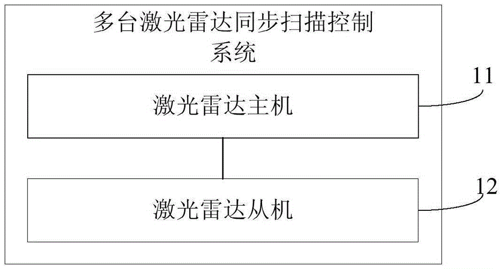
[0030] figure 1 A block diagram showing a plurality of laser radar synchronous scanning control systems according to an embodiment of the present invention; figure 1 As shown, the system includes a laser radar host 11 and at least one laser radar slave 12;

[0031] The laser radar slave 12 is used to obtain its own second closed-loop scanning frequency information, se...


PUM


Abstract

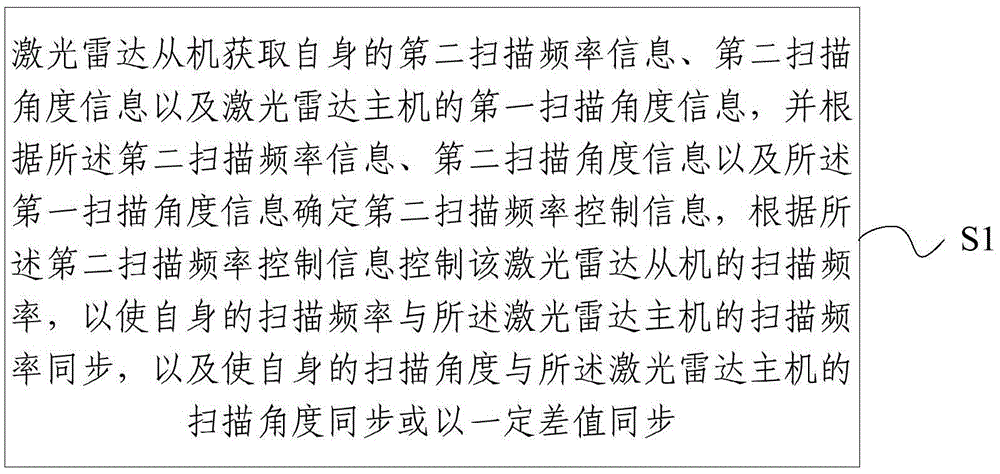
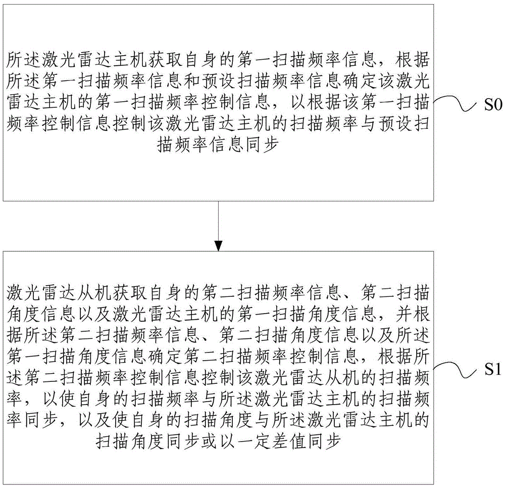
The invention relates to a multiple laser radars' synchronous scanning control system and a method wherein the system comprises a laser radar master machine and at least one laser radar slave machine. The laser radar slave machine is used to acquire its own second closed loop scanning frequency information, the second scanning angle information, and the first scanning angle information of the laser radar master machine; based on the second closed loop scanning frequency information, the second scanning angle information, and the first scanning angle information, determining the second scanning frequency control information; controlling the scanning frequency of the laser radar slave machine according to the second scanning frequency control information so that its own scanning frequency is synchronous to the scanning frequency of the laser radar and that its scanning angle is synchronous or partially synchronous with certain different to the scanning angle of the laser radar master machine. With the system and the method, it is possible to realize the synchronization of the scanning frequency and angle of multiple laser radars so as to prevent the multiple laser radars from interfering each other in their scanning, therefore, increasing the synchronization working efficiency.

Description

technical field [0001] The invention relates to the field of laser radar control, in particular to a multiple laser radar synchronous scanning control system and method. Background technique [0002] Lidar is a radar system that emits laser beams to detect characteristic quantities such as the position and speed of targets. The laser radar transmits a detection signal (laser beam) to the target, and then compares the received signal (target echo) reflected from the target with the transmitted signal, and after proper processing, the relevant information of the target can be obtained, such as the target Distance, azimuth, height, speed, attitude, and even shape parameters, so as to detect, track and identify targets such as aircraft, missiles and vehicles. [0003] In practical applications, a scanning laser radar is increasingly unable to meet the application requirements, and usually requires the use of multiple lasers for synchronous data acquisition. However, in the pro...

Claims


Application Information

Patent Timeline
IPC IPC(8): G05B19/04
CPCG05B19/04
Inventor 冀英超王泮义王庆飞
Owner BEIJING WANJI TECH
Learn More