Laser-guided AGV navigation and location method and device employing multiple laser scanners
A laser scanner, navigation and positioning technology, applied in two-dimensional position/channel control, vehicle position/route/height control, instrument and other directions, can solve the problem of limiting the application of laser-guided AGV, affecting the range of vision of laser radar, and restricting laser Guide AGV application and other issues
- Summary
- Abstract
- Description
- Claims
- Application Information
AI Technical Summary
Problems solved by technology
Method used
Image
Examples
Embodiment 1
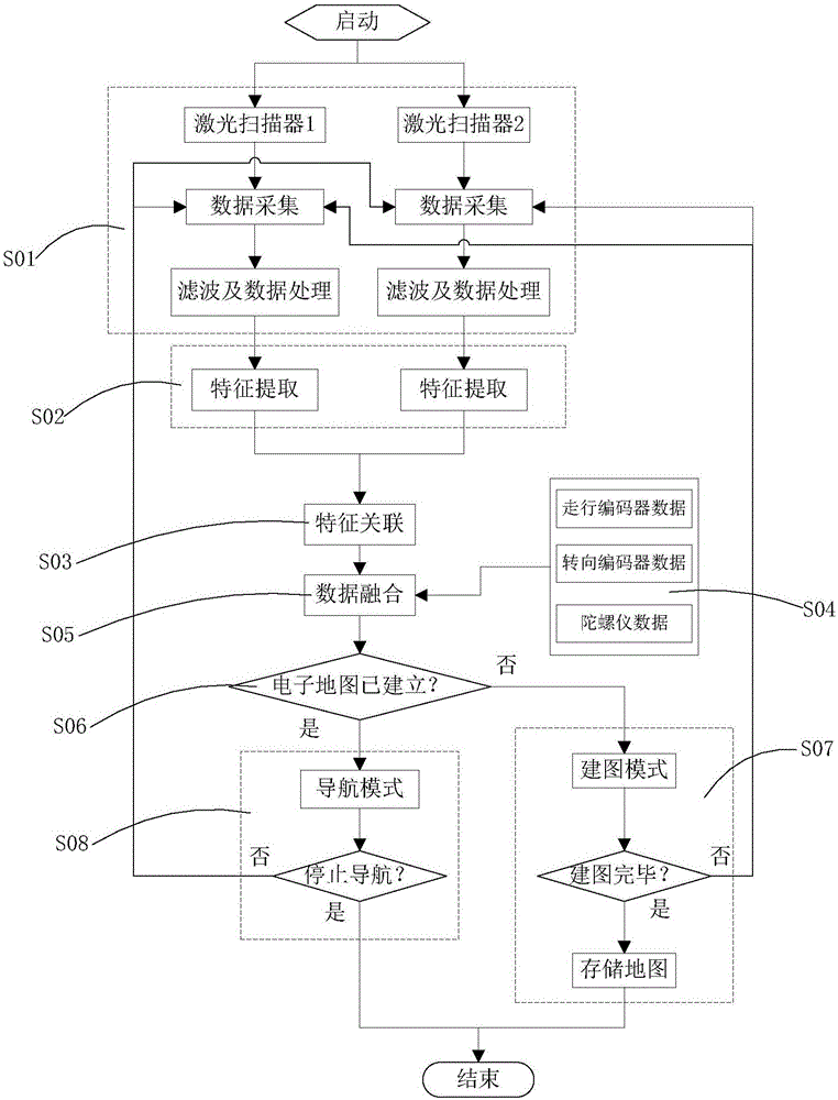
[0037] Embodiment 1: as figure 1 As shown, a laser-guided AGV navigation and positioning method with multiple laser scanners includes the following steps:
[0038] S01: At least two laser scanners are installed on the AGV body, and at least two laser scanners collect the original contour data of the scanning area A1 and the scanning area A2 respectively, and perform filtering and data preprocessing on the collected data;
[0039] S02: Perform feature extraction on the data after filtering and data preprocessing in S01 to obtain feature data of contour data; the feature data includes natural contour feature data or artificial landmark feature data or a mixture of the two. The natural contour feature data includes feature point data, straight line segment data, and arc data; the artificial landmark includes plane or cylindrical reflective stickers;
[0040] S03: extracting one or more feature data of points, straight line segments or arcs from the feature data obtained in S02, ...
Embodiment 2
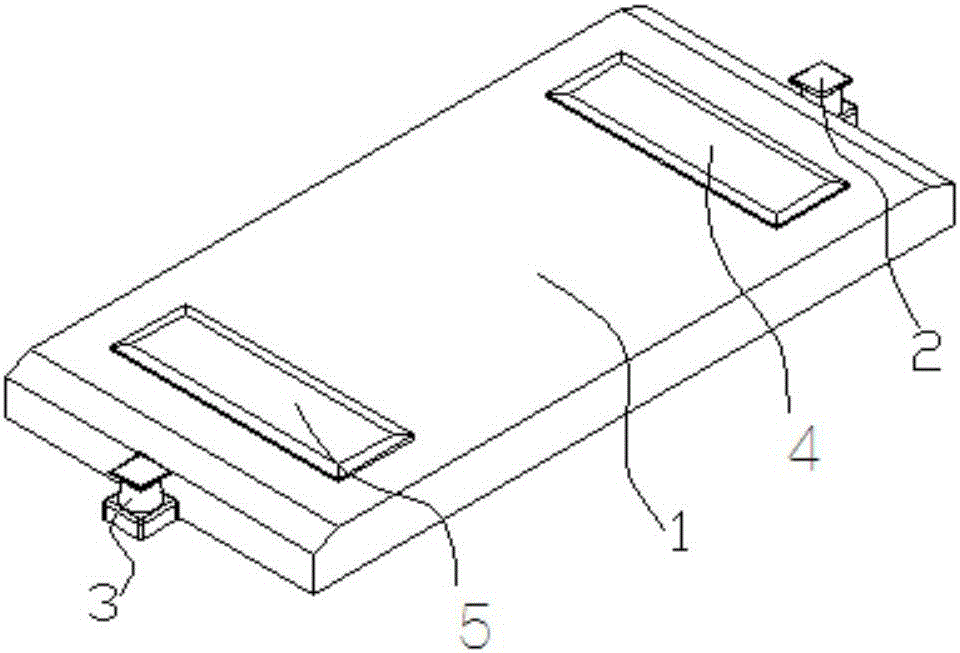
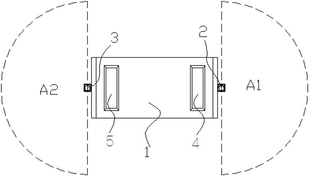
[0046] Embodiment 2: as Figure 2 ~ Figure 4 As shown, a laser-guided AGV navigation and positioning device with multiple laser scanners includes an AGV car body 1, an on-board controller placed on the AGV car body 1, and a driving device that drives the AGV car body 1 to move, and is characterized in that At least two laser scanners are installed on the AGV body 1: the first laser scanner 2 is installed at the front end of the AGV body 1, the scanning area A1 of the first laser scanner 2 is installed, and the second laser scanner is installed at the rear end of the AGV body 1. The laser scanner 3, the scanning area A2 of the second laser scanner 3.
[0047] The first laser scanner 2 and the second laser scanner 3 are installed at the front end and the rear end of the AGV body 1 respectively, both are installed along the center line of the AGV, and both are installed on the same installation plane A.
[0048] The AGV body 1 also includes a front actuator 4 at the front end of...
Embodiment 3
[0049] Embodiment 3: as Figure 5 As shown, an improvement is made on the basis of Embodiment 2, the first laser scanner 2 and the second laser scanner 3 are respectively installed at the end of the edge of the front end of the AGV car body 1 and the rear end of the AGV car body 1 At one end of different sides of the edge, the two are installed along the diagonal of the AGV and are located on the same installation plane.
[0050] The front actuator 4 and the rear actuator 5 can be hydraulic jacking devices, cam jacking mechanisms, rack and pinion, worm or screw structures.
[0051] The road wheels 6 can be mecanum wheels, bogies, steering wheels.
PUM
 Abstract
Description
Claims
Application Information
 - R&D
- Intellectual Property
- Life Sciences
- Materials
- Tech Scout
- Unparalleled Data Quality
- Higher Quality Content
- 60% Fewer Hallucinations
Browse by: Latest US Patents, China's latest patents, Technical Efficacy Thesaurus, Application Domain, Technology Topic, Popular Technical Reports.
© 2025 PatSnap. All rights reserved.Legal|Privacy policy|Modern Slavery Act Transparency Statement|Sitemap|About US| Contact US: help@patsnap.com


