Optical distortion correction method for line-scan camera

A line scan camera and optical distortion technology, applied in the field of three-dimensional measurement, can solve the problem that area scan cameras are not suitable for line scan cameras, etc., and achieve the effects of good correction effect, convenient and simple preparation, and easy operation.

Active Publication Date: 2017-05-31
HARBIN INST OF TECH
View PDF2 Cites 21 Cited by
  • Summary
  • Abstract
  • Description
  • Claims
  • Application Information

AI Technical Summary

Problems solved by technology

Area array cameras are calibrated based on two-dimensional images, while line array cameras can only obtain on...

Method used


Image

  • Optical distortion correction method for line-scan camera
  • Optical distortion correction method for line-scan camera
  • Optical distortion correction method for line-scan camera

Examples


Embodiment Construction

[0038] The technical solution of the present invention will be further described below in conjunction with the accompanying drawings, but it is not limited thereto. Any modification or equivalent replacement of the technical solution of the present invention without departing from the spirit and scope of the technical solution of the present invention should be covered by the present invention. within the scope of protection.

[0039] The invention provides a method for correcting optical distortion of a line array camera, the specific implementation steps are as follows:

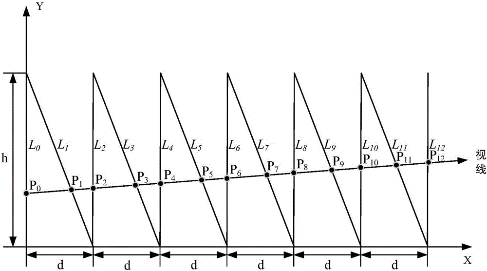
[0040] 1. Make the calibration board: such as figure 1 As shown, the calibration board is drawn with an X-Y coordinate system, 6 oblique lines and 7 straight lines, one of which is coincident with the Y axis and intersects at the origin of the coordinate axis, and the rest of the straight lines are set parallel to the Y axis and Intersecting on the X-axis, the distance between every two adjacent straight l...


PUM


Abstract

The invention discloses an optical distortion correction method for a line-scan camera. The method includes steps: step one, manufacturing a calibration board with an X-Y coordinate system, a plurality of oblique lines and a plurality of straight lines; step two, aligning the line-scan camera to the calibration board, and defining intersection points of a sight line of the line-scan camera and the straight lines and the oblique lines on the calibration board as feature points; step three, taking pictures of the calibration to obtain one-dimensional information of the feature points on an image plane of the line-scan camera, and calculating position information of each feature point; step four, subjecting camera data to one-dimensional and two-dimensional matching to adapt to a line-scan camera calibration method; step five, establishing a relationship between a world coordinate system and an image plane coordinate system to obtain intrinsic parameters and extrinsic parameters of the camera; step six, correcting camera distortion after distortion coefficients are obtained. The calibration board is simple and convenient to prepare and easy to operate; conversion from one-dimensional image data to two-dimensional image data is realized, and line-scan camera image distortion correction can be realized through coordinate transformation.

Description

technical field [0001] The invention relates to a distortion correction method of an optical system, in particular to a method for realizing distortion calibration and correction of a line array camera itself, which can be applied to three-dimensional measurement fields such as construction, transportation, and aircraft. Background technique [0002] The distortion of the optical lens changes with the change of the field of view, and directly affects the geometric position accuracy of the imaging, resulting in image distortion. For an optical system with a large field of view, distortion correction is particularly important. [0003] Optical distortion correction technology refers to the use of digital image processing methods to calibrate and correct the distortion of the optical lens itself, and eliminate the measurement error caused by image deformation. It can effectively solve the problem of reducing the geometric position accuracy of objects in the image due to lens dis...

Claims


Application Information

Patent Timeline
IPC IPC(8): G06T5/00G06T7/80
CPCG06T5/006
Inventor 朱瑶王治乐周程灏贺磊陆敏林菲
Owner HARBIN INST OF TECH
Why Eureka
Try Eureka