Moving object detection method and device

A moving target and detection method technology, which is applied in image data processing, instruments, calculations, etc., can solve the problem of inability to detect moving targets, and achieve stable and accurate detection and evaluation.

Active Publication Date: 2017-05-31
CHANGCHUN INST OF OPTICS FINE MECHANICS & PHYSICS CHINESE ACAD OF SCI
View PDF3 Cites 3 Cited by
  • Summary
  • Abstract
  • Description
  • Claims
  • Application Information

AI Technical Summary

Problems solved by technology

[0006] In view of this, the present application provides a moving target detection method and device to solve the problem that the existing technology cannot realize the detection of moving targets when the illumination changes suddenly.

Method used


Image

  • Moving object detection method and device
  • Moving object detection method and device
  • Moving object detection method and device

Examples


Embodiment Construction

[0042] The following will clearly and completely describe the technical solutions in the embodiments of the application with reference to the drawings in the embodiments of the application. Apparently, the described embodiments are only some of the embodiments of the application, not all of them. Based on the embodiments in this application, all other embodiments obtained by persons of ordinary skill in the art without making creative efforts belong to the scope of protection of this application.

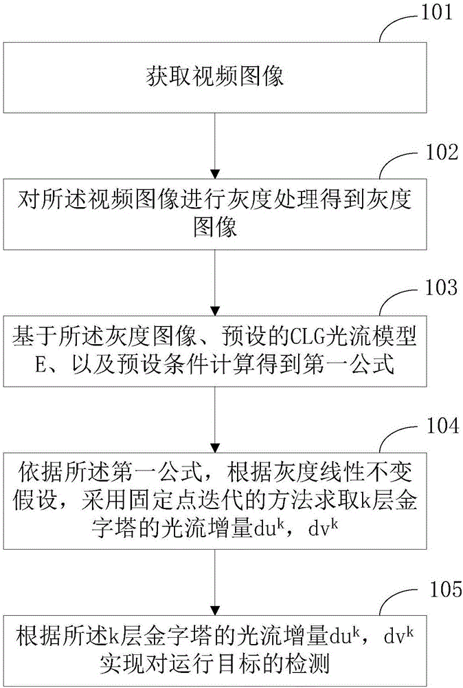
[0043] see figure 1 , which shows a flow chart of a moving target detection method provided by the present application, including:

[0044] Step 101, acquire video images.

[0045] Step 102, performing grayscale processing on the video image to obtain a grayscale image.

[0046] In this application, after each frame of video image is read, the structure and texture decomposition can be used to detect the video image. The structural texture decomposition is introduced in the prepr...


PUM


Abstract

The invention provides a moving object detection method and device. The method comprises steps as follows: acquiring a video image; performing grey processing on the video image to acquire a grey image; calculating on the basis of the grey image, a preset CLG light stream model E and a preset condition to acquire a first formula; calculating light stream increments duk and dvk of the k layer of a pyramid with a fixed point iteration method according to the first formula and the grey linear invariant hypothesis; detecting a moving object according to the light stream increments duk and dvk of the k layer of the pyramid. According to the moving object detection method, the influence of illumination change on the detection result is considered, the algorithm for evaluation of the moving object is more accurate, and accordingly, the moving object can be detected stably and accurately when the illumination suddenly changes.

Description

technical field [0001] The present application relates to the technical field of video detection, in particular to a method and device for detecting a moving object. Background technique [0002] The existing technology uses the CLG (Combined-local-Global, local global combination) optical flow model to realize the detection of moving objects. In order to reduce the sensitivity of the CLG optical flow model to illumination changes, the gradient conservation assumption is combined with the CLG optical flow model. Combined to get a new optical flow model, its energy equation is: [0003] [0004] In the above formula, I is the grayscale image, is the optical flow gradient of the grayscale image in the x and y directions, ρ is the standard deviation, K ρ Its Gaussian weight function, α is a smoothing item, w=[u,v,1] T , where u, v are the speed of the optical flow in the x, y direction, y(x) is the penalty function, Where e takes 0.0001. [0005] The inventors of the ...

Claims


Application Information

Patent Timeline
Patent Type & Authority Applications(China)
IPC IPC(8): G06T7/246
CPCG06T2207/10016
Inventor 朱明陆牧高扬
Owner CHANGCHUN INST OF OPTICS FINE MECHANICS & PHYSICS CHINESE ACAD OF SCI
Why Eureka
Try Eureka