On-off control adjustable inductor

A switch control and inductor technology, applied in the electronic field, can solve the problems of low utilization rate of magnetic core, small inductance, cumbersome control method, etc., achieve low loss, good linearity of inductance, and overcome the effect of complex adjustment scheme

Inactive Publication Date: 2017-05-31
FUJIAN UNIV OF TECH
View PDF5 Cites 0 Cited by
  • Summary
  • Abstract
  • Description
  • Claims
  • Application Information

AI Technical Summary

Problems solved by technology

The control method of this scheme is relatively cumbersome, and it also needs to use the nonlinear characteristics of the magnetic core, the utilization rate of the magnetic core is low, and the inductance control range is relatively small
[0006] In summary, the adjustable inductors in the prior art generally have the disadvantages of low core utilization, relatively large volume, relatively small inductance, and small inductance variation range.

Method used


Image

  • On-off control adjustable inductor
  • On-off control adjustable inductor
  • On-off control adjustable inductor

Examples


Embodiment 1

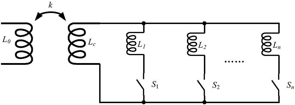
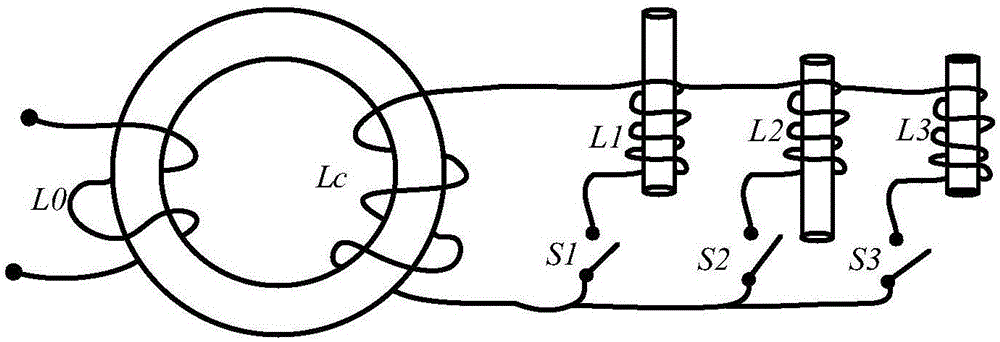
[0022] The principle of the present invention is as figure 1 shown, where L 0 main inductor winding, L c For the control inductance, L 1 ~ L n For the regulation circuit, L 0 The equivalent inductance L at the input 0eq The adjustment of the inductance is controlled by the corresponding switch S 1 ~S n Realization, the adjustment process does not require an additional bias excitation source, only needs to maintain the switch on or off.

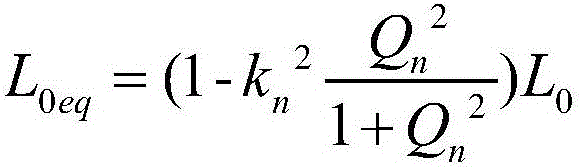
[0023] When the inductance L of a regulation circuit n When accessing, L 0 The equivalent inductance L at the input 0eq for:

[0024]

[0025] Among them, Q n To control the Q value of the inductance loop, it is defined as the inductance L c Add L n The ratio of the impedance of the control loop to the equivalent series resistance of the control loop.

[0026] k n for L 0 The equivalent coupling coefficient with the total control inductance, which is defined as:

[0027]

[0028] It can be seen that the adjustment of the...


PUM


Abstract

The invention discloses an on-off control adjustable inductor which comprises a magnetic core. A main inductor winding is arranged on the magnetic core. The magnetic core is further provided with a control inductor winding. The control inductor winding is connected with one or more adjusting circuits connected in parallel. Each adjusting circuit is controlled by an independent switch, and the equivalent inductance at the input end of a main inductor can be adjusted by turning on or off the corresponding switches. According to the adjustable inductor, the inductance of the inductor is adjustable without the need that the magnetic core works in a nonlinear area. The adjusting method has the advantages of being low in loss, good in inductance linearity and the like, and the defects that an existing adjustable inductor is complex in adjustment scheme, high in loss and the like are overcome.

Description

technical field [0001] The invention belongs to the field of electronics, and relates to a switch-controlled adjustable inductor. Background technique [0002] Inductors are important components of various power electronic power converters, which can be used to achieve functional requirements such as filtering and resonance. The inductance of general inductance devices is fixed after the design is completed, and it cannot be adjusted reasonably according to different converter working conditions to optimize the performance of the power converter. For example, in a wireless power transfer system, the failure of the resonant loop may occur depending on the transmission conditions. Therefore, by dynamically adjusting the inductance value, the performance optimization of the resonant wireless power transfer system can be realized. [0003] In order to realize the controllability of the inductance, the prior art generally utilizes the nonlinear characteristics of the magnetic c...

Claims


Application Information

Patent Timeline
Patent Type & Authority Applications(China)
IPC IPC(8): H01F29/02H01F27/40
CPCH01F29/02H01F27/40
Inventor 黄晓生林抒毅郑荣进邵明叶建盈陈彩云
Owner FUJIAN UNIV OF TECH
Why Eureka
Try Eureka