
Clamping and conveying device

A technology of conveying device and clamping mechanism, applied in switchgear, electrical components, overhead line/cable equipment, etc., can solve problems such as electric shock accident and poor safety, and achieve the effect of not occupying space, small size of equipment, and simple operation.

Active Publication Date: 2017-05-31
CHIZHOU POWER SUPPLY COMPANY STATE GRID ANHUI ELECTRIC POWER
View PDF6 Cites 8 Cited by
  • Summary
  • Abstract
  • Description
  • Claims
  • Application Information

AI Technical Summary

Problems solved by technology

However, in the process of turning on or off the high-voltage power supply, a high-voltage arc is easily formed between the contacts at both ends of the high-voltage switch. This arc is easy to contact with the operator's body and cause an electric shock accident, which is less safe.

Method used


Image

  • Clamping and conveying device
  • Clamping and conveying device
  • Clamping and conveying device

Examples


Embodiment Construction

[0032] In order to make the object, technical solution and advantages of the present invention clearer, the present invention will be further described in detail below in conjunction with the accompanying drawings and specific embodiments. It should be understood that the specific embodiments described here are only used to explain the present invention, not to limit the present invention. In addition, the technical features involved in the various embodiments of the present invention described below can be combined with each other as long as they do not constitute a conflict with each other.

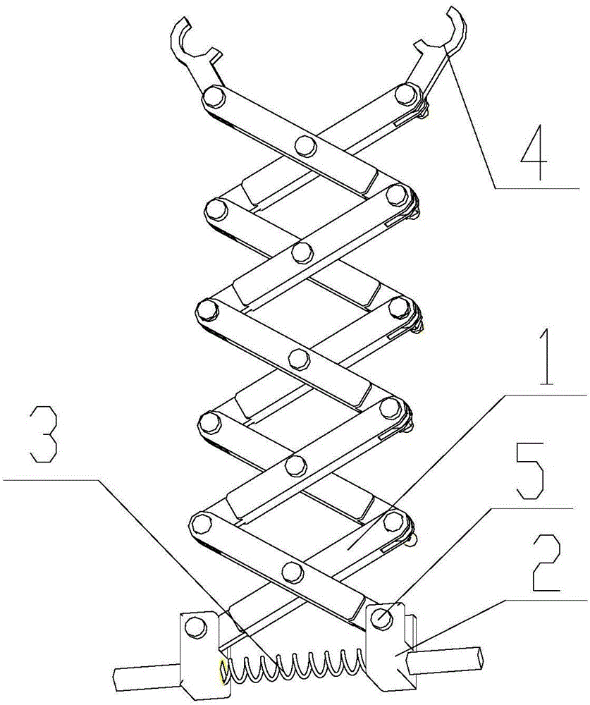
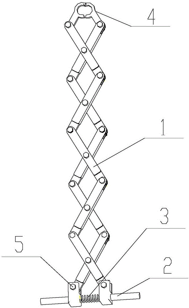
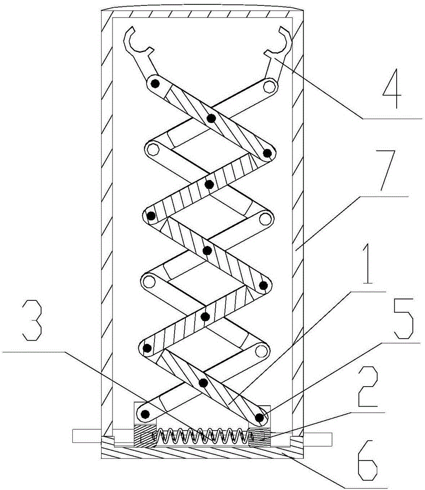
[0033] figure 1 It is a structural schematic diagram of the clamping and conveying device in the initial state of the embodiment of the present invention. A preferred embodiment of the clamping and conveying device of the present invention, such as figure 1 As shown, it includes an enlargement mechanism 1, a slide block 2, a spring 3, a claw 4 and a pin shaft 5.

[0034] Wherein, the...


PUM


Abstract

The invention discloses a clamping and conveying device, which belongs to the technical field of transmission line equipment. The device comprises a magnifying mechanism, sliders, a spring, grippers and pin shafts, wherein the magnifying mechanism is composed of a plurality of magnifying units which are connected in series, and each magnifying unit is composed of connecting rods intersecting with each other, a rotating shaft and a nut. The spring is connected with the two sliders. When the sliders are pressed by a hand, the spring is compressed, the magnifying mechanism moves telescopically, and the grippers are driven to move to make the displacement of the mechanism amplify and the grippers clamp. The clamping and conveying device disclosed by the invention can be retracted freely, is small in size, occupies less space, is easy to replace, and can be widely used for clamping cables or high voltage switches and maintaining overhead cables. The clamping and conveying device can be live operated, and no electric shock accident occurs, thus realizing high safety.

Description

technical field [0001] The invention belongs to the technical field of power transmission line equipment, and in particular relates to a clamping and conveying device. Background technique [0002] At present, with the rapid development of electric power in modern cities, cables are generally laid underground or transported by air. The method used at present is to utilize the fixed pulley to pass the cable through the pulley, and under the effect of the tractor, the cable is laid. During underground or aerial cable maintenance, it is necessary to manually transport the cable from one place to another. For example, when erecting wires at high altitude, it is necessary to manually carry the cables to climb to the utility poles. The cables are relatively heavy, and the manual carrying of the cables requires a lot of effort for the operator, and there are potential safety hazards. In these applications, there is an urgent need for a device that can be used reliably. Grips and ...

Claims


Application Information

Patent Timeline
IPC IPC(8): H01H3/02H02G1/02H02B3/00
CPCH01H3/02H02B3/00H02G1/02
Inventor 牛景平王大鹏丁永清柯乾彭友华刘根宝
Owner CHIZHOU POWER SUPPLY COMPANY STATE GRID ANHUI ELECTRIC POWER
Learn More