Coil used for wireless charging device antenna

A wireless charging and coil technology, used in antennas, loop antennas, antenna parts, etc., can solve the problems of difficulty in meeting the charging requirements of different models/specifications of electrical appliances, and the number of coil turns cannot be changed, and achieves a wide variety of materials and guarantees. The effect of stability and simple control method

Inactive Publication Date: 2017-05-31
YUNNAN KEWEI LIQUID METAL VALLEY R & D CO LTD
View PDF7 Cites 6 Cited by
  • Summary
  • Abstract
  • Description
  • Claims
  • Application Information

AI Technical Summary

Problems solved by technology

However, chargers using wireless charging technology currently on the market usually only have a single-turn coil, and the number of coil turns cannot be changed. However, the charging power and

Method used


Image

  • Coil used for wireless charging device antenna

Examples


Example Embodiment

[0024] The specific embodiments of the present invention will be described in further detail below in conjunction with the drawings and embodiments. The following examples are used to illustrate the present invention, but not to limit the scope of the present invention.
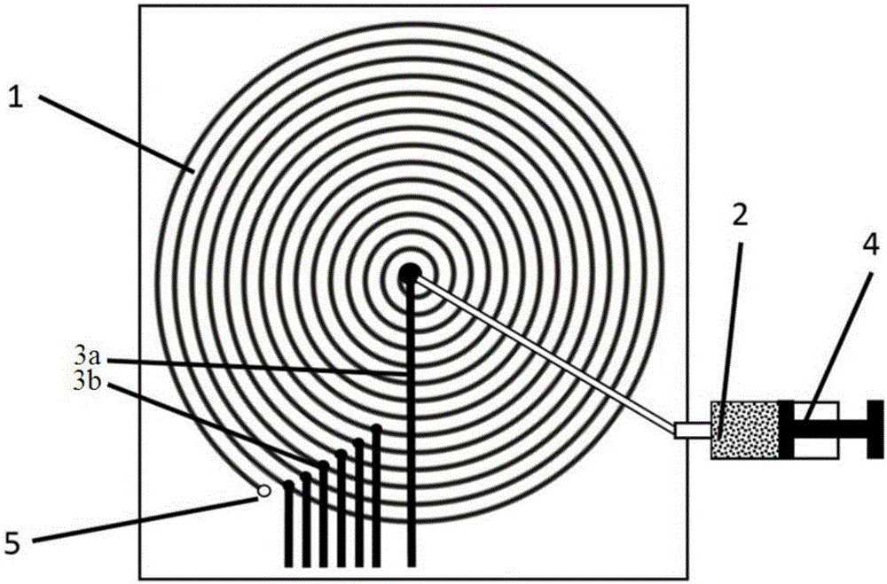
[0025] See figure 1 As shown, a coil used for an antenna of a wireless charging device includes a micro channel 1 and a liquid metal 2. The micro channel 1 is wound into a coil shape, and the liquid metal 2 is filled in the micro channel 1. The liquid metal 2 filled in the micro flow channel 1 and the micro flow channel 1 together form a conductive coil for generating an induced magnetic field to realize energy transfer.

[0026] According to actual application conditions, adjust the diameter of the micro-channel 1 to balance the resistance of the adjustment coil and the energy of the induced magnetic field generated. The diameter of the micro flow channel 1 ranges from 0.01 mm to 1 mm.

[0027] The pipe diamete...


PUM

PropertyMeasurementUnit
Diameteraaaaaaaaaa

Abstract

The invention provides a coil used for a wireless charging device antenna. The coil comprises a micro channel coiled to be coil-shaped and liquid metal fillingthe micro channel. The liquid metal is injected into or pumped out of the micro channel by a micro injection pump connected with the micro channel, but the length of the liquid metal in the micro channel is changed, so that the strength of a generated induced magnetic field is changed, and the coil can output energy with different powers. The coil used for the wireless charging device antenna provided by the invention is simple in structure and high in applicability.

Description

technical field [0001] The present invention relates to the technical field of wireless charging, and more particularly, to a coil used for an antenna of a wireless charging device. Background technique [0002] Wireless charging technology originates from wireless power transmission technology, which is divided into electromagnetic induction type, magnetic field resonance type and radio wave type. When charging with wireless charging technology, the charger and the electric device do not need to be connected by wires, but the energy is directly transmitted by the magnetic field between the two, so that the charger and the electric device do not need to expose conductive contacts, which improves the safety of use . [0003] In the electromagnetic induction wireless charging method, a coil is respectively arranged in the charger and the electric device. The alternating current of a certain frequency is passed into the primary coil installed in the charger, and the primary c...

Claims


Application Information

Patent Timeline
IPC IPC(8): H01Q7/00H01Q1/36H01Q1/50
CPCH01Q7/00H01Q1/364H01Q1/50
Inventor 国瑞盛磊邓中山刘静
Owner YUNNAN KEWEI LIQUID METAL VALLEY R & D CO LTD
Why Eureka
Try Eureka