Capacitor element compression terminal

A technology for crimping terminals and capacitors, applied in the direction of electrical components, electrical component connections, conductive connections, etc., can solve problems such as virtual welding and leakage welding, and achieve the effects of reducing self-loss, reliable crimping, and environmental protection.

Inactive Publication Date: 2017-05-31
NISSIN ELECTRIC WUXI
View PDF3 Cites 1 Cited by
  • Summary
  • Abstract
  • Description
  • Claims
  • Application Information

AI Technical Summary

Problems solved by technology

Although the brazing technology is a mature process, due to manual operation, there are cases of false welding and missing welding.

Method used


Image

  • Capacitor element compression terminal
  • Capacitor element compression terminal

Examples


Embodiment Construction

[0016] The present invention will be further described below in conjunction with the embodiments in the drawings:

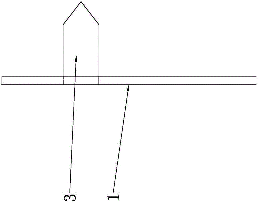
[0017] Such as Figure 1~2 As shown, the present invention mainly includes a first crimping plate 1, a second crimping plate 2 and a crimping sleeve 6.

[0018] The first crimping plate 1 and the second crimping plate 2 are connected into one body by an arc-shaped bending part 8. The first crimping plate 1 is provided with a plurality of crimping blocks 3 protruding in the direction of the second crimping plate 2, and the second crimping plate 2 is provided with a circular crimping hole 4 at a position corresponding to each pressure block 3 . When the first crimping plate 1 is pressed against the second crimping plate 2, each pressure block 3 can be pressed into a crimping hole 4 at a corresponding position. The size of the crimp hole 4 can accommodate the pressure block 3 to be pressed in.

[0019] Such as figure 1 In the illustrated embodiment, the number of the p...


PUM


Abstract

The invention relates to a compression terminal, in particular to a capacitor element compression terminal, and belongs to the technical field of a capacitor element connection structure. The capacitor element compression terminal comprises a first compression plate, a second compression plate and a compression sleeve, wherein the first compression plate and the second compression plate are connected into a whole through a bending part; a plurality of press blocks projected in a direction towards the second compression plate are arranged on the first compression plate; a compression hole is formed in a position, corresponding to each press block, on the second compression plate; the size of the compression hole meets the requirement that the press block can be pressed into the compression hole; a connecting plate extends out from the side surface of the second compression plate; the side surface of the connecting plate is connected with the compression sleeve; a compression cavity with the penetrating front and back side is formed in the compression sleeve. The capacitor element compression terminal has the advantages that an element lead-out wire is formed through mechanical compression; the compression is reliable; the contact resistance is low; the self loss of the capacitor in the use process is also reduced; the quality problem of a capacitor product due to inside insufficient soldering and missing soldering can be solved.

Description

Technical field [0001] The invention relates to a crimping terminal, in particular to a crimping terminal of a capacitor element, and belongs to the technical field of capacitor element connection structures. Background technique [0002] In the prior art, the connecting wires of the capacitor elements are basically connected by soldering, so as to form the series-parallel structure required by the capacitor design. Although the brazing technology is already a mature process, due to manual operation, there are false welding and missing welding. In addition, the solder used needs to contain a certain amount of lead to ensure the reliability of the solder, and the used flux rosin has a significant effect on the loss of the capacitor, so the emergence and replacement of new connection methods is urgently needed. Summary of the invention [0003] The purpose of the present invention is to overcome the above shortcomings, thereby providing a capacitor element crimping terminal, which ...

Claims


Application Information

Patent Timeline
Patent Type & Authority Applications(China)
IPC IPC(8): H01R11/01H01R4/18H01R4/20
CPCH01R4/18H01R4/20H01R11/01
Inventor 许伟颜红岳薛冠军曹峰吴洪林
Owner NISSIN ELECTRIC WUXI
Why Eureka
Try Eureka