
Control method for wind power, thermal power and capacitor coordinated wind and thermal bundling system after direct current block

A wind-fire bundling and control method technology, applied in wind power generation, power transmission AC network, electrical components, etc., can solve the problem of emergency control strategy that does not consider the blocking fault of the UHV DC outgoing channel, and achieve the reduction of wind-fired electric cutting machine The effect of increasing the quantity, improving safety, and optimizing the ratio of wind-fired electric cutting machine

Active Publication Date: 2017-05-31
HEFEI UNIV OF TECH
View PDF2 Cites 7 Cited by
  • Summary
  • Abstract
  • Description
  • Claims
  • Application Information

AI Technical Summary

Problems solved by technology

However, the research object of this strategy is the coordinated shutdown strategy of wind and thermal power when the transmission channel of the wind power base is short-circuited, and the emergency control strategy for the blocking failure of the UHV DC transmission channel is not considered.

Method used


Image

  • Control method for wind power, thermal power and capacitor coordinated wind and thermal bundling system after direct current block
  • Control method for wind power, thermal power and capacitor coordinated wind and thermal bundling system after direct current block
  • Control method for wind power, thermal power and capacitor coordinated wind and thermal bundling system after direct current block

Examples


Embodiment

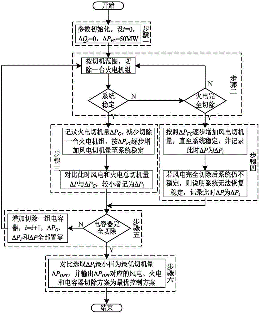
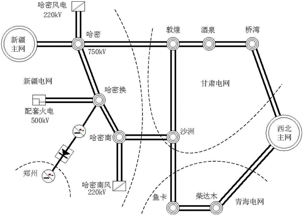
[0058] In this embodiment, the structure of the wind-fire bundling system can be found in figure 2 . The UHV DC rated voltage is ±800kV, and the rectification station is connected to the Xinjiang power grid. The active output of the thermal power unit of the wind-fire bundling system is 6600MW (10×660MW). The active output of wind power is 2850MW. A total of 16 sets of AC capacitors are configured in the UHV DC rectification station, with a total reactive power compensation capacity of 3880Mvar. Assuming that the UHV DC blockage occurs at the 100th cycle, the rectifier station capacitor is blocked and cut off with a delay of 10 cycles, and wind power and thermal power are cut off after a delay of 5 cycles.

[0059] Step 1, parameter initialization. Let ΔP FC =50MW, i=0, ΔQ i =0.

[0060] When selecting a single cut-off operation, the wind power cut-off amount ΔP FC = 50MW. Supporting capacitors are removed in units of groups, and the number of removed groups i satisf...


PUM


Abstract

The invention relates to a control method for a wind power, thermal power and capacitor coordinated wind and thermal bundling system after direct current block. The control method for the wind power, thermal power and capacitor coordinated wind and thermal bundling system after direct current block is characterized by comprising the following steps: initializing parameters at first, and switching off thermal power units one by one in a switch-off range until the system is stable or the thermal power units are switched off completely; if the system is stable, then remaining a thermal power unit, and switching off wind power units one by one until the system is stable; if the thermal power units are switched off completely, switching off the wind power units one by one until the system is stable or the wind power units are switched off completely; switching off a capacitor, switching off the thermal power units and the wind power units in the switch-off range until the system is stable or the wind power units and the thermal power units are switched off completely, recording optimal switch-off amount delta Pi of the wind power units and the thermal power units when recording different capacitor switch-off numbers until the capacitors are switched off completely; and taking a minimum amount of delta Pi as an optimal switch-off amount by comparison, and outputting the switch-off scheme at the time as an optimal control scheme. By coordination of wind power, thermal power and the capacitors, the switch-off amount of wind power and thermal power is reduced effectively, and the method can be widely applied to emergency control after direct current block of the wind and thermal bundling system.

Description

technical field [0001] The invention relates to the technical field of power system operation control, and more specifically relates to a control method after DC blocking of a wind-fire bundling system coordinated with wind-fired power and capacitors. [0002] technical background [0003] In recent years, my country's wind power has developed rapidly, and several 10-million-kilowatt-level wind power bases have been planned and built in the three northern regions and coastal areas rich in wind energy resources. However, the load level in the Sanbei area is relatively low, and the local capacity of wind power consumption is limited. The separate transmission of large-scale fluctuating wind power is not conducive to the safe and stable operation of the system. The use of wind power and thermal power bundled UHVDC transmission, while reducing the fluctuation of wind power transmission power, also improves the operating economy, and has become the preferred solution for large-sca...

Claims


Application Information

Patent Timeline
IPC IPC(8): H02J3/36H02J3/46
CPCH02J3/36H02J3/381H02J3/386H02J3/46Y02E10/76Y02E60/60
Inventor 丁明张炎韩平平
Owner HEFEI UNIV OF TECH
Learn More