Permanent magnet drive support equipment for gear machining

A technology of rotating support and permanent magnet, which is applied in the field of gear processing, can solve problems such as motor shaft bending, achieve the effects of reducing radial force, accelerating detachment speed, and facilitating maintenance

Active Publication Date: 2019-01-22
CHONGQING SUTENG MACHINERY MFG
View PDF4 Cites 0 Cited by
  • Summary
  • Abstract
  • Description
  • Claims
  • Application Information

AI Technical Summary

Problems solved by technology

[0003] At present, when using permanent magnet rotation for transmission, the permanent magnet device is directly connected to the motor shaft and the load end. At this time, the permanent magnet device is in a suspended state, and the part of the conductor disk connected to the motor shaft in the permanent magnet device The weight is supported by the motor shaft. The motor shaft is subjected to the gravity of the conductor disk in the radial direction. After a long time of use, the motor shaft is prone to bending. Therefore, there is an urgent need for a device that can support the permanent magnet device; and during installation When, usually in order to simplify the installation operation, only choose to move the motor or load to realize the connection between the two

Method used


Image

  • Permanent magnet drive support equipment for gear machining
  • Permanent magnet drive support equipment for gear machining

Examples


Embodiment Construction

[0019] The present invention will be described in further detail below by means of specific embodiments:

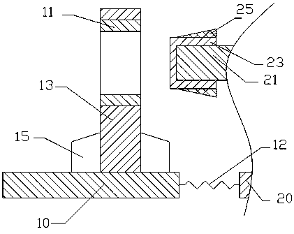
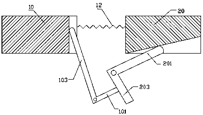
[0020] The reference signs in the accompanying drawings of the specification include: base 10, support bearing 11, extension spring 12, pole 13, support block 15, second swing end 101, second drive end 103, mounting seat 20, motor shaft 21, conductor Disk 23 , jacket 25 , first swing end 201 , first drive end 203 .

[0021] Explanation: In the manual, the first swing end refers to the swing end of the first V-shaped swing link, the first driving end refers to the drive end of the first V-shaped swing link, and the second swing end refers to the swing of the second V-shaped swing link end and the second driving end refer to the driving end of the second V-shaped swing link.

[0022] Such as figure 1 The shown permanent magnet rotating support device for gear processing includes a support base and a mounting base 20 that can move in reverse or opposite directions at the s...


PUM


Abstract

The invention relates to the technical field of gear machining, and particularly relates to permanent magnet transmission support equipment for gear machining. The permanent magnet transmission support equipment comprises a support seat and an installation seat which can be mutually driven to reversely move at the same time, wherein the support seat comprises a base and a support rod; the support rod is fixed on the base; a connection hole is formed in the upper part of the support rod; a support bearing is arranged in the connection hole; a motor is arranged on the installation seat; a motor shaft of the motor is connected with a conductor plate; the conductor plate is sleeved with an outer sleeve capable of shrinking under the action force of the support bearing; the outer sleeve can slide into the support bearing and is provided with an inner cavity containing lubricating oil; and the outer sleeve is provided with a seal cover capable of being opened outwards. The invention aims at providing equipment capable of supporting a permanent magnet in a transmission mechanism.

Description

technical field [0001] The invention relates to the technical field of gear processing, in particular to permanent magnet rotation support equipment for gear processing. Background technique [0002] Gear processing includes gear blank processing, tooth surface processing, heat treatment process and tooth surface finishing. The power is mostly provided by the motor. The existing permanent magnet rotation uses the air gap between the copper conductor and the permanent magnet to realize the torque transmission from the motor to the load. The permanent magnet device is mainly composed of a conductor rotor and a permanent magnet rotor. The conductor rotor is fixed on the motor shaft, the permanent magnet rotor is fixed on the load shaft, and there is an air gap between the conductor rotor and the permanent magnet rotor, so that the motor and the load are changed from the original mechanical connection to the magnetic connection. After the permanent magnet rotation is used, the ...

Claims


Application Information

Patent Timeline
Patent Type & Authority Patents(China)
IPC IPC(8): H02K49/00
CPCH02K49/00
Inventor 王全中
Owner CHONGQING SUTENG MACHINERY MFG
Why Eureka
Try Eureka