Constant voltage and constant current dual-mode buck DC power supply circuit based on compensation topology
What is Al technical title?
Al technical title is built by PatSnap Al team. It summarizes the technical point description of the patent document.
A technology for compensating topology and DC power supply, which is applied in the direction of conversion equipment without intermediate conversion to AC, and can solve problems such as affecting the quality of DC power output power, long adjustment time, and system hazards
Active Publication Date: 2019-08-06
HARBIN ENG UNIV
View PDF2 Cites 0 Cited by
Summary
Abstract
Description
Claims
Application Information
AI Technical Summary
This helps you quickly interpret patents by identifying the three key elements:
Problems solved by technology
Method used
Benefits of technology
Problems solved by technology
However, when the load changes suddenly (the load suddenly increases or decreases), the energy storage of the inductance and capacitance cannot meet the needs of the load instantly, so the circuit generates a large dynamic adjustment process under the adjustment of the controller, and the constant voltage mode The lower voltage fluctuation amplitude is larger, the current amplitude fluctuation is larger in constant current mode, and the adjustment time is longer in both cases
This seriously affects the output power quality of the DC power supply, and may even cause great harm to the entire system
For the problem of how to improve the dynamic response of DC power supply, researchers have proposed many solutions, but most of the solutions are only limited to improving the dynamic response of DC power supply constant voltage mode, and cannot be applied to both constant voltage and constant current modes at the same time.
Method used
Image
Click on the blue label to locate the original text in one second.
Reading with bidirectional positioning of images and text.
Examples
Embodiment Construction
[0035] The following examples describe the present invention in more detail.
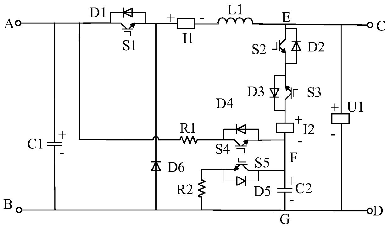
[0036] combine figure 1 The constant voltage and constant current dual-mode BUCK type DC power supply circuit based on compensation topology of the present invention is mainly composed of capacitor C1, capacitor C2, resistor R1, resistor R2, inductor L1, diode D1, diode D2, diode D3, diode D4, diode D5 , diode D6, power electronic switching device S1, power electronic switching device S2, power electronic switching device S3, power electronic switching device S4, power electronic switching device S5, current sensor I1, current sensor I2, voltage sensor U1, input terminal A , Input terminal B, output terminal C, output terminal D and other components. Among them, diode D1, diode D2, diode D3, diode D4, and diode D5 are the anti-parallel diodes of power electronic switching device S1, power electronic switching device S2, power electronic switching device S3, power electronic switching device S4, and...
PUM
Abstract
The invention provides a constant-voltage and constant-current dual-mode BUCK type direct-current power circuit on the basis of compensation topology. The constant-voltage and constant-current dual-mode BUCK type direct-current power circuit comprises a first capacitor, a second capacitor, a first resistor, a second resistor, an inductor, a first diode, a second diode, a third diode, a fourth diode, a fifth diode, a sixth diode, a first power electronic switch device, a second power electronic switch device, a third power electronic switch device, a fourth power electronic switch device, a fifth power electronic switch device, a first current sensor, a second current sensor, a voltage sensor, a first input wiring terminal, a second input wiring terminal, a third input wiring terminal and a fourth input wiring terminal. The constant-voltage and constant-current dual-mode BUCK type direct-current power circuit has the advantages that the problems that most traditional BUCK type direct-current power sources only can work in constant-voltage modes, are long in dynamic regulation time under the condition of sudden change of load, are high in voltage fluctuation amplitude in the constant-voltage modes and are high in current fluctuation amplitude in constant-current modes can be solved; voltages can be reduced on the premise that currents of input direct-current voltages are basically stable, stable direct-current voltages can be provided for load in constant-voltage modes by topological structures of a direct-current power main circuit and corresponding control strategies, and stable direct currents can be provided for the load in constant-current modes by the topological structures of the direct-current power main circuit and the corresponding control strategies.
Description
technical field [0001] The invention relates to a DC constant voltage / constant current power supply circuit. Background technique [0002] In actual engineering, both constant voltage mode power supply and constant current mode power supply are required in many occasions, such as battery charging and so on. Because of its simple structure and easy control, the BUCK circuit is often used as the main circuit of a step-down constant voltage or constant current power supply (the DC power supply mentioned below, unless otherwise specified, refers to a DC power supply with a BUCK circuit structure). Under the action of a reasonable control strategy (such as PI control of output voltage closed-loop in constant voltage mode, and PI control of inductor current closed-loop in constant current mode), this kind of DC power supply has high accuracy of output voltage and current in steady state. Good stability. However, when the load changes suddenly (the load suddenly increases or decr...
Claims
Application Information
Patent Timeline
Application Date:The date an application was filed.
Publication Date:The date a patent or application was officially published.
First Publication Date:The earliest publication date of a patent with the same application number.
Issue Date:Publication date of the patent grant document.
PCT Entry Date:The Entry date of PCT National Phase.
Estimated Expiry Date:The statutory expiry date of a patent right according to the Patent Law, and it is the longest term of protection that the patent right can achieve without the termination of the patent right due to other reasons(Term extension factor has been taken into account ).
Invalid Date:Actual expiry date is based on effective date or publication date of legal transaction data of invalid patent.