
Novel two-stage multi-level power inversion system

A multi-level inverter and power inverter technology, which is applied in the direction of converting DC power input to DC power output, converting AC power input to DC power output, and adjusting electrical variables, etc., which can solve the problem of reducing system reliability and increasing DC power. Power supply output ripple, large current harmonics and other issues, to achieve the effect of excellent control quality, small system work efficiency, and small current harmonics

Inactive Publication Date: 2017-05-31
NANJING UNIV OF AERONAUTICS & ASTRONAUTICS
View PDF3 Cites 8 Cited by
  • Summary
  • Abstract
  • Description
  • Claims
  • Application Information

AI Technical Summary

Problems solved by technology

[0003] However, the control effect of the traditional full-bridge inverter is not good, mainly due to the following four reasons:
[0004] 1. The traditional DC power supply connected to the full-bridge inverter can only achieve step-down output. If the voltage level of the load terminal is high, the traditional full-bridge inverter cannot meet its output requirements;
[0005] 2. The input current of the traditional full-bridge inverter is discontinuous current and there are low-frequency ripples, which will increase the output ripple of the DC power supply and reduce the reliability of the DC power supply;
[0006] 3. When using a two-level full-bridge inverter, if the switching frequency is low, the current harmonics will be large, which will seriously increase system loss and reduce system reliability;
[0007] 4. When the clamp type multi-level inverter is used, there is a defect that the midpoint voltage oscillates and even tends to be unbalanced

Method used


Image

  • Novel two-stage multi-level power inversion system
  • Novel two-stage multi-level power inversion system
  • Novel two-stage multi-level power inversion system

Examples


Embodiment Construction

[0029] The technical scheme of the present invention will be further described in detail below in conjunction with the accompanying drawings:

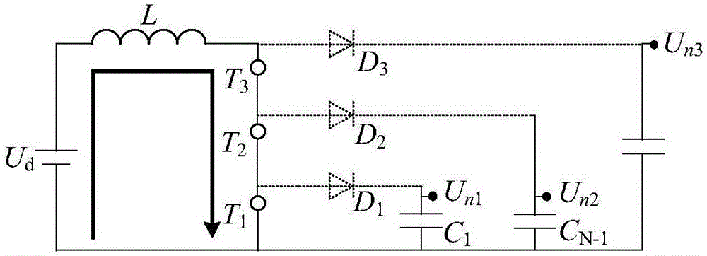
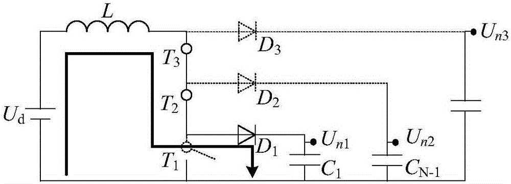
[0030] The present invention is a novel two-stage multi-level power inverter system, such as figure 1 As shown, a front-stage multi-output DC-DC converter and a diode clamped multi-level inverter are cascaded as the power topology. Through the voltage closed-loop control of the front-stage DC-DC converter, the power supply boost and the active control of the midpoint voltage of the multi-level inverter are realized. The latter-stage clamped multi-level inverter can realize motor drive and grid-connected inversion. Change, or island grid operation.

[0031] The invention discloses a novel two-stage multi-level power inverter system, which includes a front-stage multi-output DC-DC converter, a back-stage multi-level inverter and a load end. The front-stage multi-output DC-DC converter and the rear-stage multi-level inverter are independentl...


PUM


Abstract

The invention discloses a novel two-stage multi-level power inversion system. A front-stage multi-way output DC-DC (Direct Current-Direct Current) convertor and a diode clamping multi-level inverter are cascaded to serve as power topology. Voltage boosting of a power supply and active control on neutral-point voltage of the multi-level inverter can be realized by closed-loop control on voltage of the front-stage DC-DC convertor; and the back-stage clamping multi-level inverter can realize functions of motor driving, grid-connected inversion, isolated grid operation and the like. A method can realize the voltage boosting by the front-stage DC-DC convertor at the same withstand voltage of switching tubes; limitation of a voltage class of a DC power supply can be overcome; a high voltage class load can be adapted; the front-stage DC-DC convertor overcomes an influence of interrupted current input or low-frequency pulsation of the traditional inverter on the DC power supply; the problem of difficult balance of the neutral-point voltage of the clamping multi-level inverter can be overcome by utilizing the active control ability of the front-stage DC-DC convertor on the voltage; and multi-level inverter control of variable neutral-point voltage can be realized to acquire low current.

Description

Technical field [0001] The invention relates to a novel two-stage multi-level power inverter system, which belongs to the technical field of electric energy conversion. Background technique [0002] The power inverter system (also known as the frequency converter) is the core component of the motor drive, grid connection, island grid and other systems. Traditional motor drive, grid-connected, island grid and other systems are powered by a DC power supply connected to a full-bridge inverter, and the inverter output is realized through PWM modulation of the full-bridge inverter. [0003] However, the traditional full-bridge inverter control effect is not good, mainly due to the following four reasons: [0004] 1. The traditional DC power supply connected to the full-bridge inverter can only achieve step-down output. If the load terminal voltage level is higher, the traditional full-bridge inverter cannot meet its output requirements; [0005] 2. The input current of the traditional ful...

Claims


Application Information

Patent Timeline
IPC IPC(8): H02M7/537H02M3/158
CPCH02M3/1584H02M7/537H02M1/007H02M1/009
Inventor 顾聪王晓琳邓智泉赵星晨
Owner NANJING UNIV OF AERONAUTICS & ASTRONAUTICS
Learn More