Two-way Boost converter

A converter and circuit technology, applied in the direction of converting DC power input to DC power output, instruments, adjusting electrical variables, etc. Small, cost-reducing effect

Inactive Publication Date: 2012-10-17
SUZHOU VOCATIONAL UNIV
View PDF2 Cites 0 Cited by
  • Summary
  • Abstract
  • Description
  • Claims
  • Application Information

AI Technical Summary

Problems solved by technology

When charging the battery, this bidirectional DC converter is equivalent to a Boost converter; when the battery supplies power to the outside, it is equivalent to a Buck converter (step-down converter); the Bi Boost-buck converter can only achieve boost when the energy is transmitted in one direction. Voltage, can not achieve bidirectional boost, can not meet the design requirements

Method used


Image

  • Two-way Boost converter

Examples


Embodiment Construction

[0012] The preferred embodiments of the present invention will be described in detail below in conjunction with the accompanying drawings, so that the advantages and features of the invention can be more easily understood by those skilled in the art, so as to define the protection scope of the present invention more clearly.

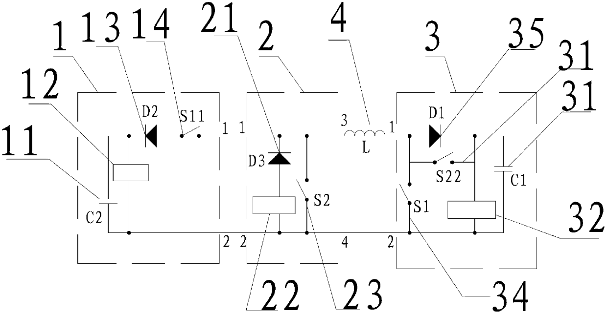
[0013] see figure 1 , the embodiment of the present invention includes:

[0014] A bidirectional Boost converter, the bidirectional Boost converter includes a first circuit 1, a second circuit 2, a third circuit 3 and a high-frequency inductor 4, the pins 1 and 2 of the first circuit 1 are respectively connected to the second Connect pins 1 and 2 of circuit 2; pin 3 of the second circuit 2 is connected to pin 1 of the third circuit 3 in series with pin 4 of the high-frequency inductor; pin 4 of the second circuit 2 is connected to pin 4 of the third circuit 3 The 2 terminal pins are connected.

[0015] The first circuit 1 includes a capacitor C2 11, a ...


PUM


Abstract

The invention discloses a two-way Boost converter. The two-way Boost converter comprises a first circuit, a second circuit, a third circuit and a high-frequency inductor, wherein wiring pins 1, 2 of the first circuit are sequentially and respectively connected with wiring pins 1, 2 of the second circuit, a wiring pin 3 of the second circuit is connected in series with the high-frequency inductor and then connected with a wiring pin 1 of the third circuit, and a wiring pin 4 of the second circuit is connected with a wiring pin 2 of the third circuit. Through the way, the two-way Boost converter can realize two-way energy transfer, and the boosting output of direct current in two directions. Few components are used in the design, so that the production cost is effectively reduced and the two-way Boost converter is smaller in volume.

Description

technical field [0001] The invention relates to the technical field of power electronics, in particular to a bidirectional Boost converter. Background technique [0002] A DC converter is a power converter that converts one kind of direct current into another kind of direct current. Conventional DC converters can only transfer energy in one direction from the input end to the output end, and cannot transfer energy in two directions. In new energy power supply systems such as solar energy and wind energy, due to the instability of solar energy and wind energy, and the fact that the power generation time and power consumption time are often inconsistent, batteries must be used as intermediate energy storage links. The storage battery is sometimes charged in the system and sometimes discharged externally. When charging, a DC converter should be used to match the photovoltaic power generation or wind power generation with the battery voltage, while considering the maximum powe...

Claims


Application Information

Patent Timeline
Patent Type & Authority Applications(China)
IPC IPC(8): H02M3/155H02J7/35H05B37/02
Inventor 张波汪义旺朱臻
Owner SUZHOU VOCATIONAL UNIV
Why Eureka
Try Eureka