Loop detection method and device
A loop detection and forwarding path technology, applied in the network field, can solve problems such as time-consuming and low efficiency, and achieve the effect of improving inspection efficiency
- Summary
- Abstract
- Description
- Claims
- Application Information
AI Technical Summary
Problems solved by technology
Method used
Image

Examples
Embodiment Construction
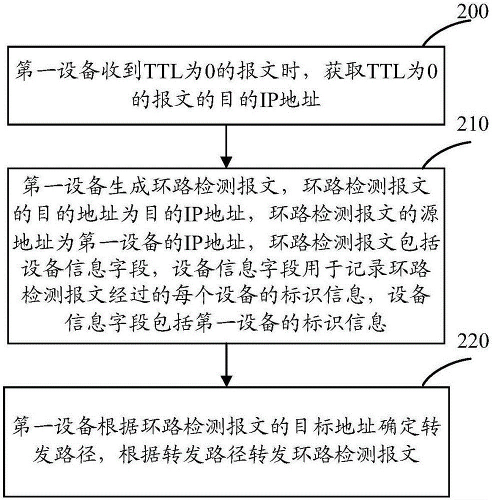
[0054] Embodiments of the present invention will be described below in conjunction with the accompanying drawings.
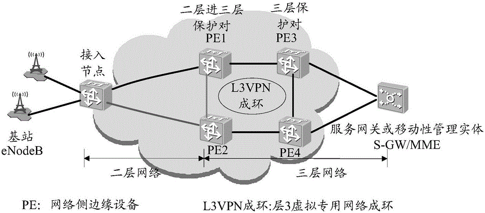
[0055] The device referred to in the embodiment of the present invention may be a network-side edge device, or a router, or a packet transport network (Package Transport Network, PTN)) device or the like.
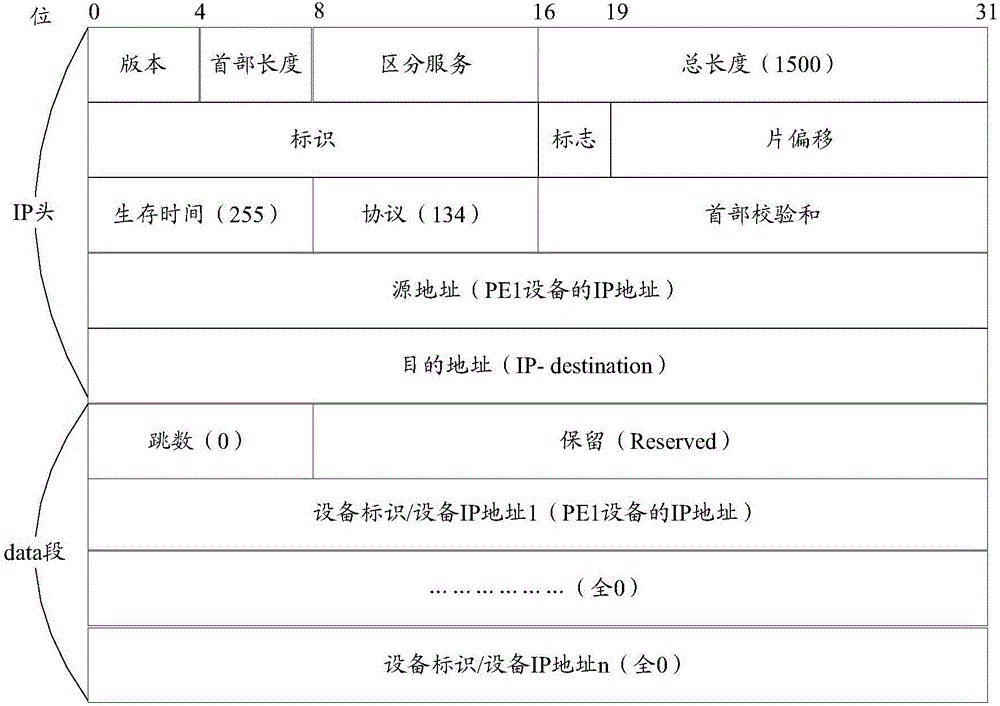
[0056] The time-to-live (Time To Live, TTL) field referred to in the embodiment of the present invention is used to indicate the maximum number of network segments allowed to pass before the IP data packet is discarded by the router, that is, the maximum number of hops that the IP data packet can forward in the computer network . The TTL is set by the sending host to prevent packets from continually looping endlessly over the IP internetwork. The maximum value for TTL is 255.
[0057] Specifically, the TTL field is set by the sender of the IP data packet. On the entire forwarding path of the IP data packet from the source address to the destination address,...
PUM
 Abstract
Description
Claims
Application Information
 - R&D
- Intellectual Property
- Life Sciences
- Materials
- Tech Scout
- Unparalleled Data Quality
- Higher Quality Content
- 60% Fewer Hallucinations
Browse by: Latest US Patents, China's latest patents, Technical Efficacy Thesaurus, Application Domain, Technology Topic, Popular Technical Reports.
© 2025 PatSnap. All rights reserved.Legal|Privacy policy|Modern Slavery Act Transparency Statement|Sitemap|About US| Contact US: help@patsnap.com