Heating body for electrically heatable glow plug with axially pressed heating insert and associated production method

A technology of heating body and glow plug, which is applied in the direction of heating element shape, combustion method, electric heating device, etc., and can solve problems such as deterioration of electrical properties, deterioration of function and quality of glow plugs, etc.

Inactive Publication Date: 2019-07-09
ROBERT BOSCH GMBH
View PDF6 Cites 0 Cited by
  • Summary
  • Abstract
  • Description
  • Claims
  • Application Information

AI Technical Summary

Problems solved by technology

In any case, the electrical properties of the coil 91 and accordingly the function and quality of the glow plug 9 are significantly deteriorated thereby.

Method used


Image

  • Heating body for electrically heatable glow plug with axially pressed heating insert and associated production method
  • Heating body for electrically heatable glow plug with axially pressed heating insert and associated production method
  • Heating body for electrically heatable glow plug with axially pressed heating insert and associated production method

Examples


Embodiment Construction

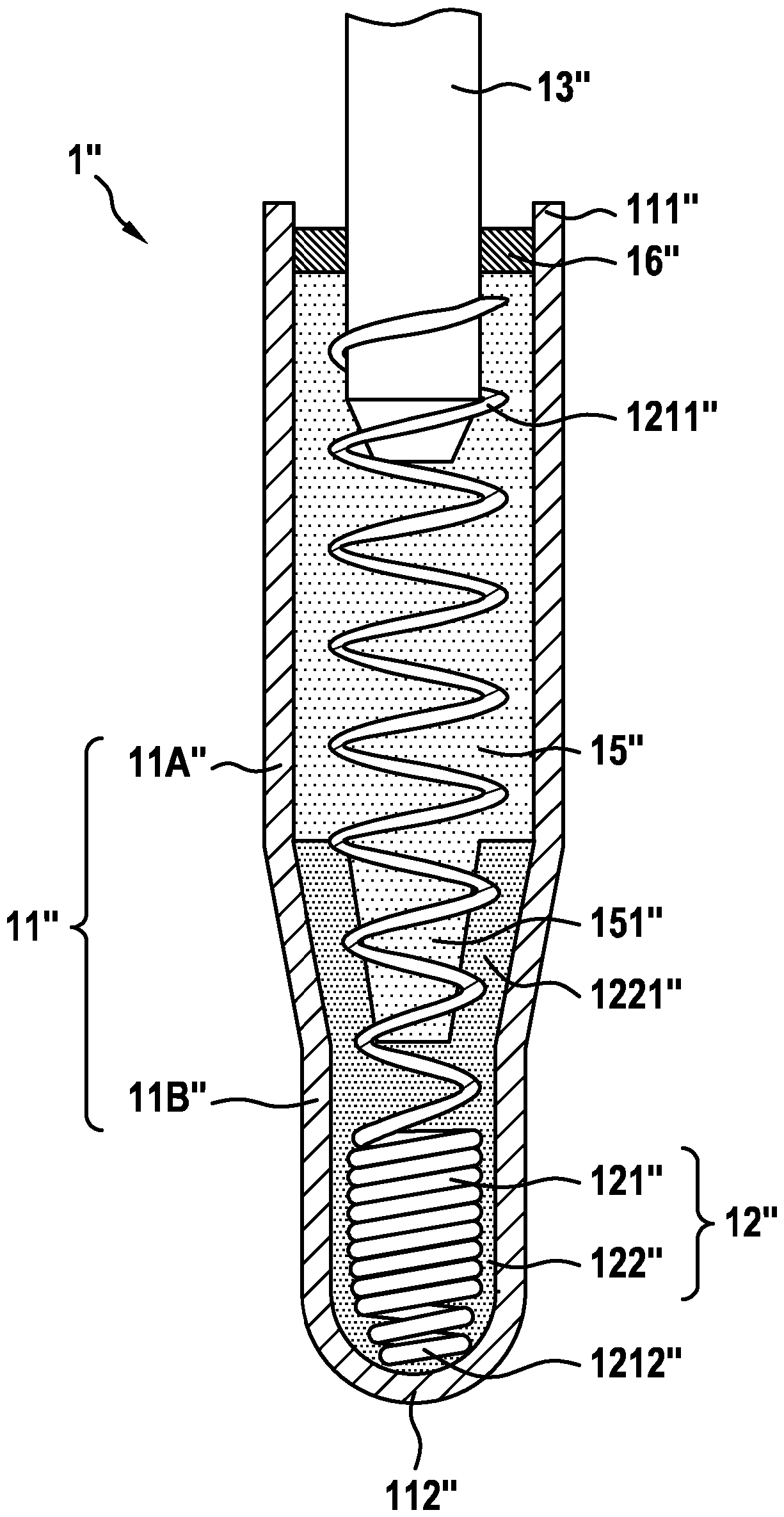
[0039] exist figure 1 A heating body 1 according to the invention for a glow plug according to a first preferred embodiment is shown in , in which components such as the housing as well as insulating components and coupling elements have been omitted for the sake of clarity. exist figure 1 The heating body 1 shown in has a metallic glow tube 11, a heating insert 12 arranged inside it (the heating insert is arranged inside the closed end 112 of said glow tube 11) and a coupling pin 13, which The coupling pin is connected to the heating insert 12 via the contact element 14 . The heating insert 12 and the coupling pin 13 are inserted into the glow tube 11 sideways from the open end 111 of the glow tube 11 , which end is opposite to the closed end of the glow tube 11 . The ends 112 are arranged opposite each other.

[0040] The heating insert 12 consists of an extruded composite from a coil 121 and insulating powder 122 . A first end 1211 of coil 121 , which is arranged oppo...


PUM


Abstract

The invention relates to a heating element (1) for an electrically heatable sheathed glow plug, comprising a glow tube (11) and a heating insert (12) which is disposed in the glow tube (11) and includes at least one coil (121) and an insulating powder (122) that is pressed together with the coil; the heating insert (12) is an axially pressed part. The invention further relates to a method for manufacturing a heating element (1) for an electrically heatable sheathed glow plug.

Description

technical field [0001] The invention relates to a heating body for an electrically heatable glow plug or glow plug, and in particular to a glow plug-heating body with a heating insert arranged therein, wherein the heating insert comprises at least A coil and insulating powder that function as an electric resistance element. The invention also relates to a method for producing such a heating body according to the invention for an electrically heatable glow plug. Background technique [0002] Known glow plugs are used here not only as cold start aids in chambers of internal combustion engines (such as, for example, the prechamber, swirl chamber or combustion chamber of self-igniting diesel motors with compressed air), but also in other fields of application For example as a propellant heating element in common rail injection systems of flex-fuel drive systems, as a cold start aid when starting gas turbines and oil heaters operated with kerosene, etc. As cold start aids in kn...

Claims


Application Information

Patent Timeline
Patent Type & Authority Patents(China)
IPC IPC(8): F23Q7/00
CPCF23Q7/001F23Q2007/004H05B3/48H05B2203/027
Inventor B.塞龙尼科拉特
Owner ROBERT BOSCH GMBH
Why Eureka
Try Eureka